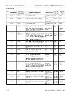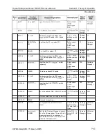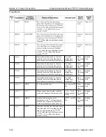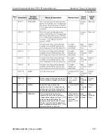
Toyota Orderpicker Model
15
Service Manual
Section
9.
Theory of Operation
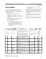
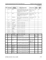
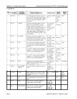
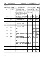
Pinout Matrix
00700-CL222-05, 1 5
March
2005
JPC
JPC
JPC
JPC 1-2
JPClO-1
JPC
J
PC9-2
J
PC9-4
LED
6
LED
7
LED 8
LED 9
LED 10
1
1.3 VP
B+F
B+F
B+F
12VP
2
DGND
Takes LED 6 to B- when the C M wants it
turned on.
Takes LED
7
to B- when the C M wants it
turned on.
Takes LED 8 to B- when the C M wants it
turned on.
Takes LED 9 to B- when the C M wants it
turned on.
Takes LED 10 to B- when the C M wants it
turned on.
Supplies voltage to the lights on the
Display card when
is present on
the STM.
Supplies
for optional devices on the
carriage like Bin Lights and
RF
terminals.
Supplies B- for optional devices on the
carriage like Bin Lights and
RF
terminals.
Supplies
for optional devices on the
carriage like Bin Lights and
RF
terminals.
Supplies B- for optional devices on the
carriage like Bin Lights and
RF
terminals.
Same as
on the STM.
Same as
on the STM.
Same as
on the STM.
Same as
on the STM.
Same as JPT9 on the STM.
Same as JPT9 on the STM.
Same as JPT9 on the STM.
LED
LED
WRT
LED
LED
WRT
LED
LED On=
WRT
LED
LED
WRT
LED
LED On=
WRT
with key switch
closed
with battery
plugged in. OV
unplugged
wrt TP4
(B-)
with battery
plugged in. OV
unplugged
wrt TP4
(B-)
Carriage
Manager
Carriage
Manager
Carriage
Manager
Carriage
Manager
Carriage
Manager
Carriage
Manager
Carriage
Manager
Carriage
Manager
Carriage
Manager
Carriage
Manager
Display
Card
Display
Card
Display
Card
Display
Card
Display
Card
Display
Card
Optional
Device
Optional
Device
Optional
Device
Optional
Device
Summary of Contents for 7BPUE15
Page 1: ...Serial Numbers Service Manual 80 001 and up 7BPUE15...
Page 2: ......
Page 5: ......
Page 58: ......
Page 144: ......
Page 299: ......
Page 301: ......
Page 346: ......
Page 358: ......
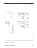
Page 386: ...Figure A 6 Cont Elec Schematic Sheet I Part 2 of 2 00700 CL222 05 15 March 2005...
Page 389: ......
Page 391: ...Hydraulic Schematic RES Figure A 9 Hydraulic Schematic 00700 CL222 05 15 March 2005...
Page 400: ......
Page 401: ...Printed in the USA...

