Section
6. Codes and Tests
Toyota Orderpicker Model
15 Service Manual
Maintenance Mode
Maintenance Mode
Maintenance mode allows you to test individual
circuits of switches and inputs while the lift
truck is stationary or under normal operation.
For example, if you suspect the lift switch is
bad, you can verify the switch circuit input to
the
manager.
Enter the maintenance mode. See "Enter"
below. There are two methods for entering
Maintenance Mode, using the
pedal or
using the horn button. After you enter
maintenance mode, follow the instructions in
"General Testing."
Pedal Method
1. Turn the key switch ON. The horn beeps
three (3) times after self-diagnostics is
complete.
2. Within 10 seconds after the three (3) horn
beeps, step on and off the
pedal
3-6 times. The horn will start clicking
when the truck is in maintenance mode.
N
OTE
:
The
circuit must be
transitioned 12 times to enter
maintenance mode. If both switches (S2
and S23) are working properly, you only
need to step on and off the pedal 3
times. If one is not working, you need to
step on and off 6 times.
Horn Button Method
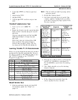
1. Turn the key switch OFF.
2. Hold the horn button and turn the key
switch ON. Do
not release the horn button.
3. When the BDI display clears, release the
horn button.
4. While the BDI display is clear, press and
release the horn button once. Each time
you press the horn button, one BDI LED
lights.
5.
Wait for the BDI display to clear. A clear
display indicates the first digit was
accepted.
N
OTE
:
You must enter the second digit within 3
seconds of entering the first digit.
6. Press and release the horn button once
more.
7. Wait a few seconds for the BDI display to
clear again. All the BDI LEDs will flash to
indicate the password was accepted and
the truck is in Maintenance Mode.
General Testing
1. Enter maintenance mode. See "Enter" on
page 6-4.
2. Request a n operation.
lift, etc.
When the switch turns on or off, or
an
analog input crosses a threshold, the
truck determines whether the circuit is
good or bad.
If the
circuit is
good,
the horn clicks and
the heartbeat LEDs on the
manager and carriage manager, and the
steer indicator LEDs on the operator
display blink during the operator request.
If the
circuit is
bad,
the horn does not
click and the LEDs do not blink during the
operator request.
The following standard switches can be tested
in maintenance mode:
Steer Home Switch
(S2 and S23)
Horn
24" Limit
see Note below
60" Height
see Note below
150" Height
see Note below
Emergency power off (S2 1)
N
OTE
:
To test S6, S7, S24, S25, S29 and S60,
step on
pedal and lift the
operator platform. Each switch is tested
a s it passes its activation rail.
The following optional switches can also be
tested in maintenance mode:
00700-CL222-05, 1
5 March 2005
Summary of Contents for 7BPUE15
Page 1: ...Serial Numbers Service Manual 80 001 and up 7BPUE15...
Page 2: ......
Page 5: ......
Page 58: ......
Page 144: ......
Page 299: ......
Page 301: ......
Page 346: ......
Page 358: ......
Page 386: ...Figure A 6 Cont Elec Schematic Sheet I Part 2 of 2 00700 CL222 05 15 March 2005...
Page 389: ......
Page 391: ...Hydraulic Schematic RES Figure A 9 Hydraulic Schematic 00700 CL222 05 15 March 2005...
Page 400: ......
Page 401: ...Printed in the USA...


