Section 7 . Component Procedures
Toyota Orderpicker Model
15 Service Manual
Battery Procedures
Electrical Components
Battery Procedures
Before working on the battery, review
Battery Safety, beginning on page 2-6.
Batteries for this lift truck weigh
between 920 and 2000 Ib.
(41
8
to 908
kg). Use extreme care during
replacement. Use a suitable battery
moving device or hoist for lifting. Do not
extend a battery more than
1
of its
length outside the battery compartment
without being attached to a
battery-moving device.
N
OTE
:
The distance from the floor to the top of
the battery rollers is 12.25 inches (3
1.12
cm)
.
Battery
Location
The battery connector is located a t the
front-right of the tractor, above the battery.
Removal, Replacement, and
Installation
When replacing battery cable ends,
remove only one end at a time from the
connector, to avoid the cable ends
touching and causing a short circuit. Do
not allow the metal cable end to touch
the battery. Use insulated tools and
avoid contact with battery case or cable
ends.
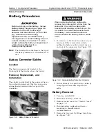
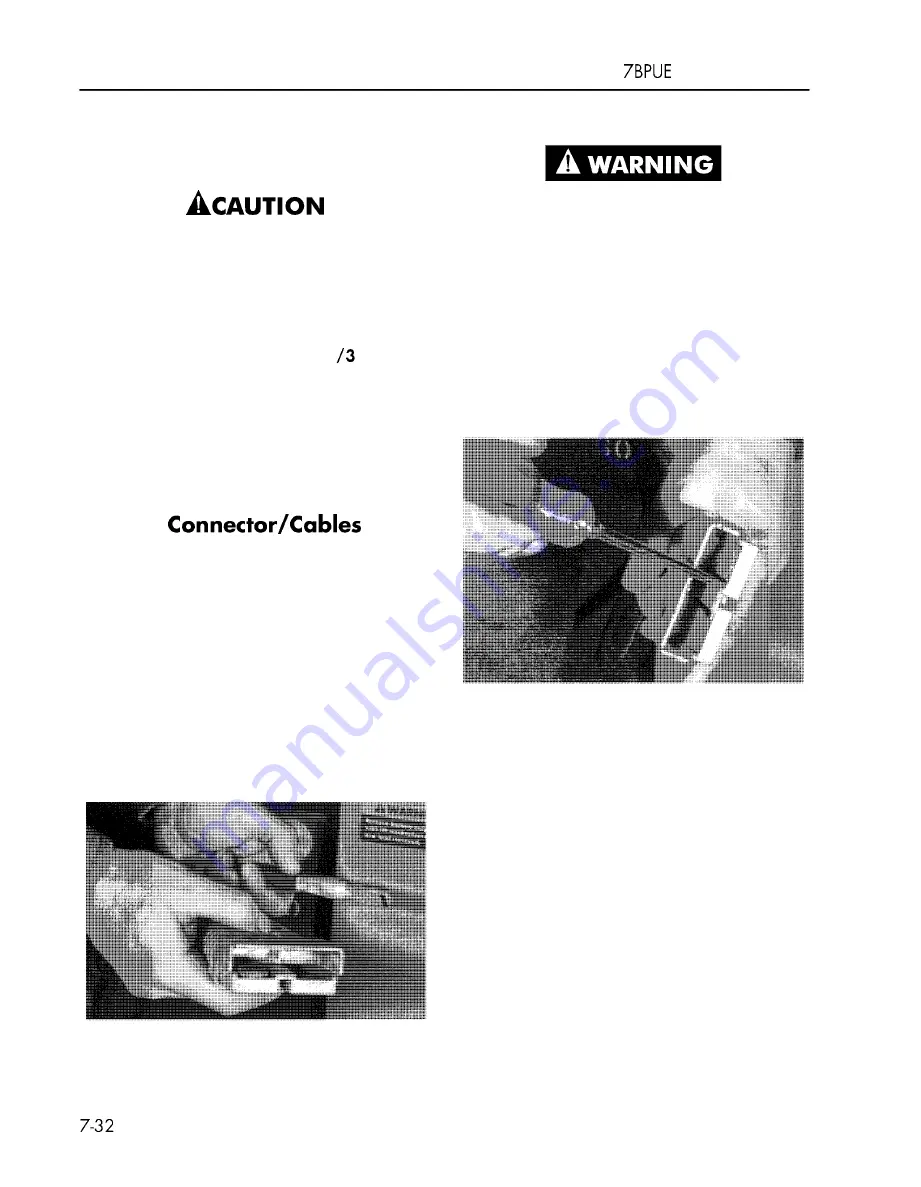
1. To remove a cable from the connector, you
must push this retainer down while
pulling the battery cable towards the rear
and out of the connector. See Figure 7-39.
Figure 7-39. Removing Battery Cable from Connector
The cables to either half of the connector have a
lip on their forward end. This lip snaps over a
2.
Do not attempt to repair battery cables by
spring-loaded retainer which is part of the
crimping new terminals. Replace the
connector.
cable.
Battery Removal
1. Turn key switch OFF.
2.
Disconnect battery connector.
3. Remove tractor cover. See 'Tractor Covers"
on page 7- 1 1.
4. Position battery replacement device
according to manufacturer's
recommendation.
5. Remove battery gate by lifting straight up.
See Figure 7-40.
Figure 7-38. Battery Cable and Connector
00700-CL222-05, 1
5 March 2005
Summary of Contents for 7BPUE15
Page 1: ...Serial Numbers Service Manual 80 001 and up 7BPUE15...
Page 2: ......
Page 5: ......
Page 58: ......
Page 144: ......
Page 299: ......
Page 301: ......
Page 346: ......
Page 358: ......
Page 386: ...Figure A 6 Cont Elec Schematic Sheet I Part 2 of 2 00700 CL222 05 15 March 2005...
Page 389: ......
Page 391: ...Hydraulic Schematic RES Figure A 9 Hydraulic Schematic 00700 CL222 05 15 March 2005...
Page 400: ......
Page 401: ...Printed in the USA...


