Section 7 . Component Procedures
Toyota Orderpicker Model
15 Service Manual
Switches (General)
Electrical Components
4.
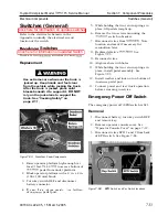
Loosen two screws on backside of EPO
4. Reconnect battery connector and check
switch.
operation.
5. Hold lower half of switch, push in and
5. Turn key switch OFF and disconnect
rotate top half
counterclockwise to
battery connector.
unlock halves of EPO switch.
6.
Install operator console cover.
N
OTE
:
The switch may t u r n hard.
7. Connect battery and test operation before
6.
Lift top half of EPO switch from bezel.
returning truck to service.
Installation
1. Insert lower portion of EPO switch in its
hole in bezel.
2.
Slide upper half of EPO switch over lower
half until it is seated. Rotate top half
clockwise to lock.
3.
Tighten screws on backside of EPO switch.
See Figure 7-84.
4.
Reconnect wires to back of the EPO
switch.
5. Install operator console cover.
6.
Connect power and test truck operation
before returning truck to service.
Key
Switch
This lift truck is equipped with a two position
key switch
1)
,
which energizes all
truck operations.
Removal
1. Turn key switch OFF and disconnect
battery connector.
2.
Remove operator console cover.
3.
Remove mounting n u t from stem of key
switch. See Figure 7-84.
4. Remove key switch.
5. Disconnect wires from bottom of key
switch.
Installation
1. Connect wires to terminals.
2.
Install new key switch and tighten locking
nut.
3.
Secure mounting n u t on key switch stem.
00700-CL222-05, 1
5 March 2005
Summary of Contents for 7BPUE15
Page 1: ...Serial Numbers Service Manual 80 001 and up 7BPUE15...
Page 2: ......
Page 5: ......
Page 58: ......
Page 144: ......
Page 299: ......
Page 301: ......
Page 346: ......
Page 358: ......
Page 386: ...Figure A 6 Cont Elec Schematic Sheet I Part 2 of 2 00700 CL222 05 15 March 2005...
Page 389: ......
Page 391: ...Hydraulic Schematic RES Figure A 9 Hydraulic Schematic 00700 CL222 05 15 March 2005...
Page 400: ......
Page 401: ...Printed in the USA...


