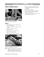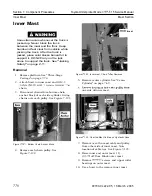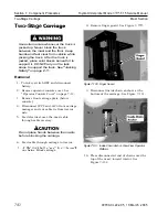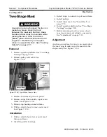
Toyota Orderpicker Model
15 Service Manual
Section 7. Component Procedures
Mast Section
Mast Bearings
Figure
7- 135. Mast Bearings and Shims
Shimming
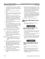
Use extreme care whenever the truck
is
jacked up. Never block the truck
between the mast and the floor. Keep
hands and feet clear from vehicle while
jacking the truck. After the truck
is
jacked, place solid blocks beneath it to
support it. DO NOT rely on the jack
alone to support the truck. See "Jacking
Safety" on page
2- 1 1.
1. Turn key switch OFF and disconnect
battery.
2.
Attach suitable hoist and lift carriage until
you can reach bearings.
3. Remove bearings and shims.
4. Replace shims a s required.
N
OTE
:
Shim evenly on both sides until the
smallest shim will not fit between the
bearing and the upright.
Do
not over
shim.
Shimming a mast is done to ensure a smooth
running unit which is not too tight or too loose.
Total movement between the bearings and mast
should be between 0.030 to 0.045 in. (0.76 to
1.14 mm).
Mast Bearings
If any marks are found within the masts or
main frame where the rollers have been
running, they should be removed with a
sanding disk with 8 0 grit paper. Do not attempt
to remove all marks, only the ridges.
Figure
7- 136. Staging of Mast Prior to Shimming Bearings
A properly adjusted mast should show no more
than a 0.5 in. (13 mm) mark where the roller
touches the respective mast or main frame. The
assembly should be shimmed to the tightest
spot on the assembly (as the rollers r u n u p and
down the rail). Small areas that are slightly
higher than the rest of the web can be buffed to
avoid shimming the major portion of the rail too
loose. While shimming the mast, the masts and
carriage must be loose enough to slide them in
and out by hand. Shimming the assembly in a n
upright position can result in shimming that is
too tight and could cause premature wear.
00700-CL222-05, 1 5 March 2005
Summary of Contents for 7BPUE15
Page 1: ...Serial Numbers Service Manual 80 001 and up 7BPUE15...
Page 2: ......
Page 5: ......
Page 58: ......
Page 144: ......
Page 299: ......
Page 301: ......
Page 346: ......
Page 358: ......
Page 386: ...Figure A 6 Cont Elec Schematic Sheet I Part 2 of 2 00700 CL222 05 15 March 2005...
Page 389: ......
Page 391: ...Hydraulic Schematic RES Figure A 9 Hydraulic Schematic 00700 CL222 05 15 March 2005...
Page 400: ......
Page 401: ...Printed in the USA...

