Section
9. Theory of Operation
Toyota Orderpicker Model
15 Service Manual
Battery Plugged In
Battery Plugged
In
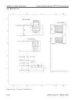
Refer to the schematic in Figure 9-2 on
page 9-6.
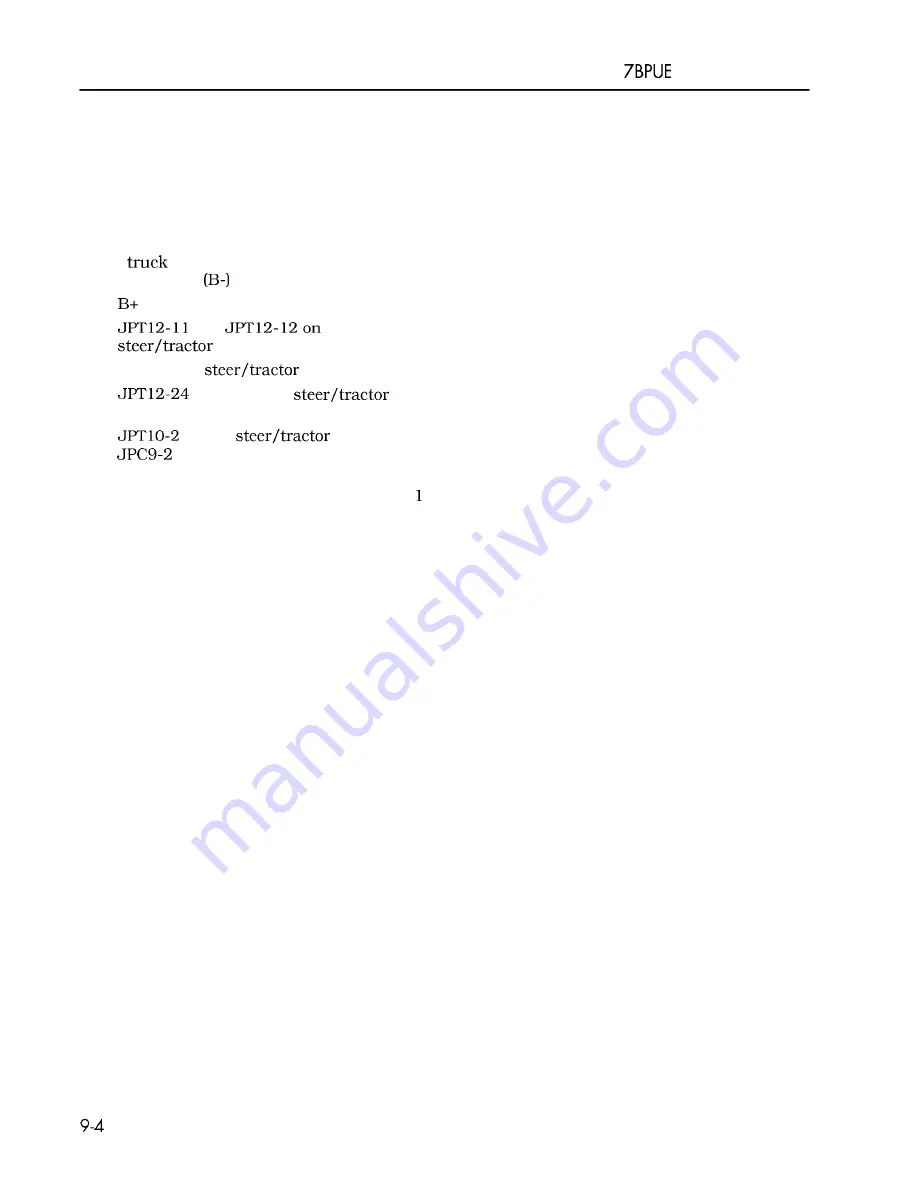
When a properly charged battery is connected
to the
battery positive is present with
reference to TP4
a t the following points:
1.
side (PC- 1) of the open PC contactor tip
2.
and
the
manager (STM)
3. FU2 on the
manager
4.
(horn) on the
Manager a s B+F
5.
on the
manager to
on the carriage manager (CM) a s
B+F
6. JPC 1 1-5 on the carriage manager to
S 1-
a s B+F
7. JPC 10- 1 and JPC 10-2 on the carriage
manager a s B+F
00700-CL222-05, 1
5 March 2005
Summary of Contents for 7BPUE15
Page 1: ...Serial Numbers Service Manual 80 001 and up 7BPUE15...
Page 2: ......
Page 5: ......
Page 58: ......
Page 144: ......
Page 299: ......
Page 301: ......
Page 346: ......
Page 358: ......
Page 386: ...Figure A 6 Cont Elec Schematic Sheet I Part 2 of 2 00700 CL222 05 15 March 2005...
Page 389: ......
Page 391: ...Hydraulic Schematic RES Figure A 9 Hydraulic Schematic 00700 CL222 05 15 March 2005...
Page 400: ......
Page 401: ...Printed in the USA...


