Toyota Orderpicker Model
15 Service Manual
Section 5. Troubleshooting
Contactors
Testing Resistance
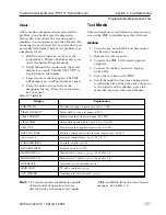
Visually inspect the contactor for any signs of
burning or physical damage.
1.
Turn key switch
OFF
and disconnect
battery connector.
2.
Disconnect two wires marked
X
and Y
contactor.
3 .
Connect one lead of ohmmeter to
X
contactor lead and one to the Y contactor
lead.
4. The reading should be between 20 and 40
ohms. If resistance is outside that range,
replace contactor.
Contactors
Examine the fuse for signs of overheating,
discoloration, cracking, or other physical
damage. You should be able to see if the fuse is
blown through the fuse window. Replace the
fuse if you find damage.
To test a fuse, remove it or isolate it from the
electrical circuit. Do this by removing the fuse
from the truck or by removing all the
connections from one side of the fuse.
Use a n ohmmeter set to
scale and measure
the resistance across the fuse. The resistance
should be less than
1
ohm.
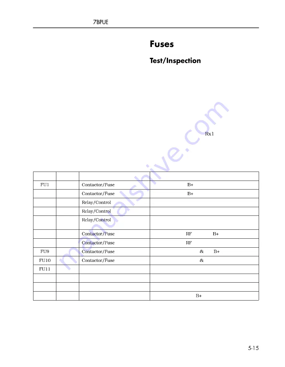
Table
5- 1 .
Fuse Chart
00700-CL222-05, 1 5 March 2005
Fuse
FU2
FU3
FU4
FU5
FU7
FU8
FU12
FU13
FU14
Amps
1 5
1 5
3 5 0
4 0
3 5 0 or
5 0 0
2
2
6
6
1 0
1 0
1 0
2
Location
Panel
Panel
Fuse Panel
Fuse Panel
Fuse Panel
Panel
Panel
Panel
Panel
Aux Power Fuse Panel
Aux Power Fuse Panel
Aux Power Fuse Panel
Aux Power Fuse Panel
Function
Control Fuse for
PC
Control Fuse for
Power fuse for TM
Power fuse for SM
Power fuse for Lift Pump Motor
Control fuse for
Terminal
Control fuse for
Terminal B-
Control fuse for Lights
F a n
Control fuse for Lights
F a n B-
Control fuse for carriage heater (CS Option)
Control fuse for tractor heaters (CS Option)
Control fuse for carriage heaters (CS Option)
Control fuse for GM,
ESTOP (WG Option)
Summary of Contents for 7BPUE15
Page 1: ...Serial Numbers Service Manual 80 001 and up 7BPUE15...
Page 2: ......
Page 5: ......
Page 58: ......
Page 144: ......
Page 299: ......
Page 301: ......
Page 346: ......
Page 358: ......
Page 386: ...Figure A 6 Cont Elec Schematic Sheet I Part 2 of 2 00700 CL222 05 15 March 2005...
Page 389: ......
Page 391: ...Hydraulic Schematic RES Figure A 9 Hydraulic Schematic 00700 CL222 05 15 March 2005...
Page 400: ......
Page 401: ...Printed in the USA...


