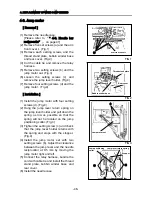
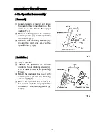
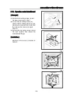

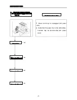
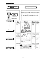
4-18. Operation control circuit board
[Removal]
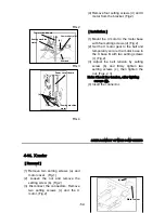
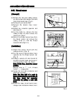
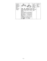
(1) Remove four setting screws (a) and
the base cover rear R. (Fig.1)
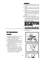
(2) Loosen the two setting screws (b),
remove the two setting screws (c) and
disconnect connectors CN12 and CN7,
then remove the case cover upper.
(Fig.2,3)
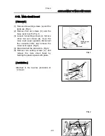
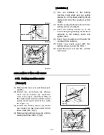
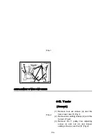
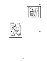
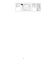
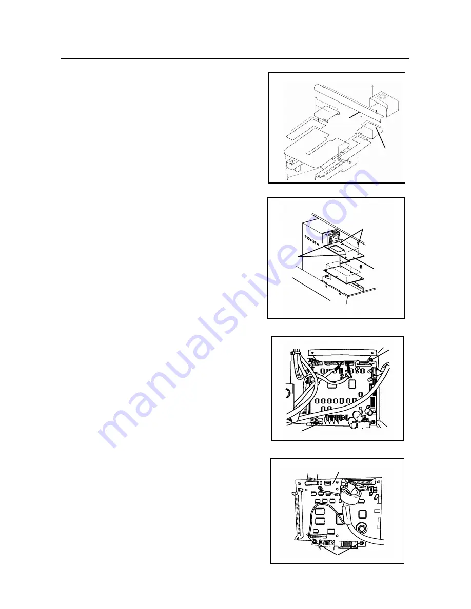
(3) Remove the two setting screws (d) and
the resin spacers, then remove the
console board (Fig.4).
[Installation]
Attached in the reverse procedure of
removal.
4.REPLACEMENT OF MAIN COMPONENTS
FIG.1
FIG.2
(a)
Base cover
rear R
(c)
(b)
Case cover
upper
CN12
CN7
FIG.3
(d)
Console board
-58-
Summary of Contents for ESP9000
Page 1: ...SERVICE MANUAL Embroidery Machine ESP9000 15 needles...
Page 2: ......
Page 13: ...FIG 3 48...
Page 24: ...FIG 4 59...
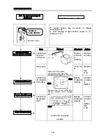
Page 36: ...Connection of connector CN 10 Must be connected correctly Replace See P 47 CN10 11...
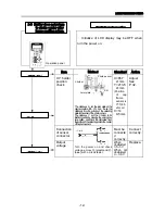
Page 40: ...Picker height C 7 9 mm when piker solenoid is ON Adjust See P 27 15...
Page 58: ...FIG 2 FIG 3 201 3 0 1 0 3 mm 22...
Page 63: ...FIG 4 e Drive arm FIG 5 27...
Page 70: ...FIG 3 34...
Page 72: ...FIG 2 FIG 3 201 3 0 1 0 3 mm 22...
Page 74: ...FIG 2 FIG 3 Needle bar Stopper Needle bar Connecting stud 24...
Page 77: ...FIG 4 e Drive arm FIG 5 27...
Page 84: ...FIG 3 34...
Page 86: ...FIG 4 31...
Page 88: ...FIG 4 33...
Page 90: ...FIG 2 35...
Page 93: ...2 a Sensor arm 3 38...
Page 95: ...FIG 3 FIG 4 VR6 Power supply board 40...
Page 97: ...FIG 3 FIG 4 0 5 to 0 8mm 0 2mm or less Hook support hook support 37...
Page 100: ...FIG 4 40...
Page 103: ...FIG 2 Needle bar c Top dead center stopper needle bar connecting stud FIG 3 43...
Page 105: ...FIG 5 45...
Page 111: ...Printed in Japan 2002 8...