
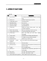

2.TROUBLESHOOTING
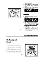
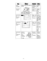
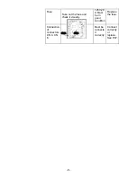
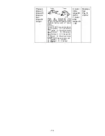
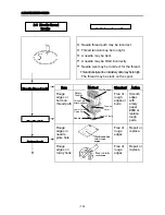
・ The embroidery frame holder may be jammed.
・ The cloth may be stuck at a table corner.
・ The embroidery frame may be interfering.
.
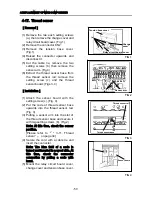
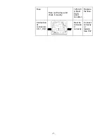
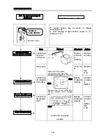
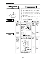
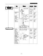
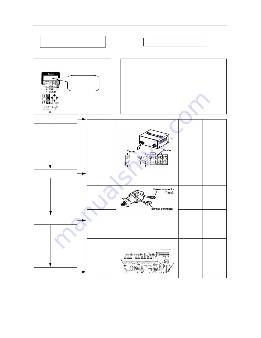
Item
Method
Standard Action
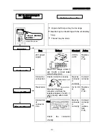
24V power
supply
Check the voltage across ⑤
and⑪with a circuit tester, while
shorting⑧to⑨.
24.0 to
24.5V
Replace
See
P.44.
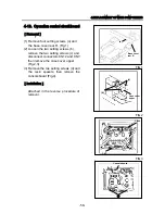
Connection
of power
and sensor
connectors
Must be
connecte
d
correctly
Connect
correctly
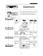
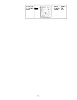
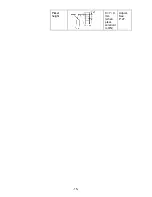
Resistance Disconnect
the
power
connector, and check the
resistance between①and②,
① and ③ , ② and ③ with a
circuit tester.
0.4 to 0.8
Ω
Replace.
See
P.51.
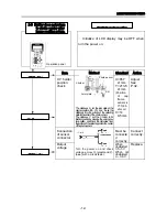
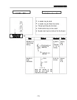
Connection
of
connectors
CN 1, CN 4
Check
the
connector
visually.
Must be
connecte
d
correctly
Connect
correctly
or
replace.
See
P.45.
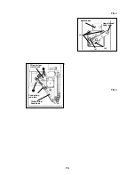
CN1
CN4
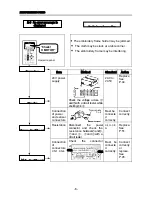
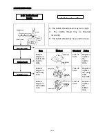
Power box
X motor
Power circuit board
Main circuit board
Operation panel
“Check!
X MOTOR ”
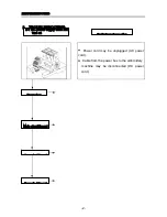
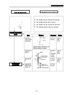
Preliminary inspection
2-3
An error message is
displayed
-6-
Summary of Contents for ESP9000
Page 1: ...SERVICE MANUAL Embroidery Machine ESP9000 15 needles...
Page 2: ......
Page 13: ...FIG 3 48...
Page 24: ...FIG 4 59...
Page 36: ...Connection of connector CN 10 Must be connected correctly Replace See P 47 CN10 11...
Page 40: ...Picker height C 7 9 mm when piker solenoid is ON Adjust See P 27 15...
Page 58: ...FIG 2 FIG 3 201 3 0 1 0 3 mm 22...
Page 63: ...FIG 4 e Drive arm FIG 5 27...
Page 70: ...FIG 3 34...
Page 72: ...FIG 2 FIG 3 201 3 0 1 0 3 mm 22...
Page 74: ...FIG 2 FIG 3 Needle bar Stopper Needle bar Connecting stud 24...
Page 77: ...FIG 4 e Drive arm FIG 5 27...
Page 84: ...FIG 3 34...
Page 86: ...FIG 4 31...
Page 88: ...FIG 4 33...
Page 90: ...FIG 2 35...
Page 93: ...2 a Sensor arm 3 38...
Page 95: ...FIG 3 FIG 4 VR6 Power supply board 40...
Page 97: ...FIG 3 FIG 4 0 5 to 0 8mm 0 2mm or less Hook support hook support 37...
Page 100: ...FIG 4 40...
Page 103: ...FIG 2 Needle bar c Top dead center stopper needle bar connecting stud FIG 3 43...
Page 105: ...FIG 5 45...
Page 111: ...Printed in Japan 2002 8...