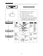
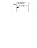
Item
Method
Standard Action
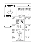
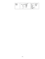
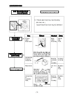
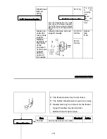
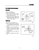
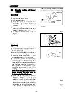
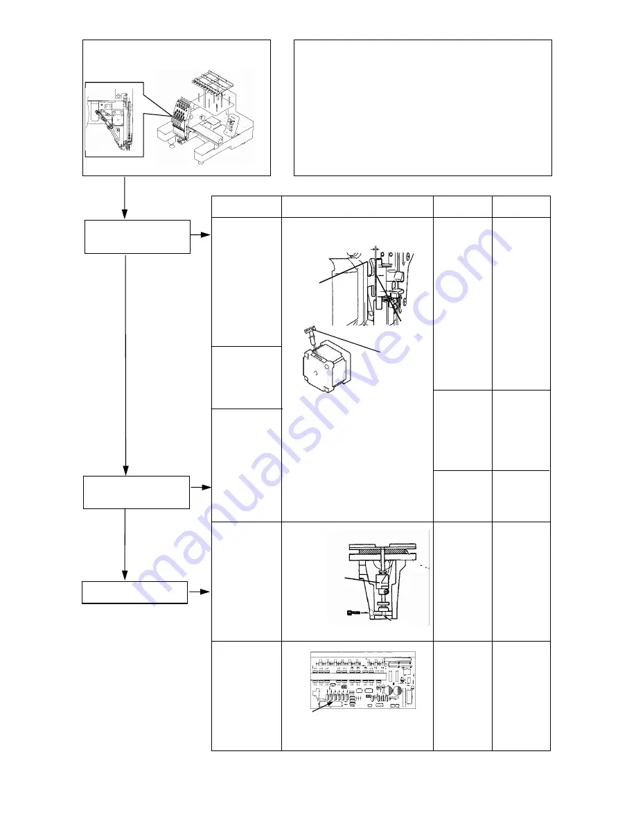
Installation
position of
jump motor
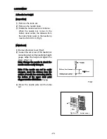
Connection
of power
connector
Resistance
Remove the rear cover and
check
Disconnect
the
power
connector and check the
resistance between ① and
⑤, ② and ⑥, ③and ⑤, ④
and ⑥ with a circuit tester.
A=0.5 ±
0.1mm
Must be
connecte
d
correctly.
4.8~6.0
Ω
Adjust.
See
P.29.
Connect
correctly.
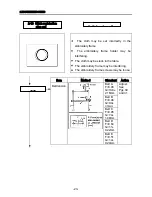
Replace.
See
P.47.
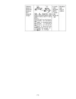
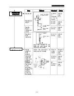
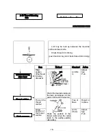
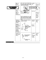
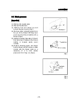
Wrong
movement
or damage
of needle
bar
reciprocato
r
Free of
burrs
Replace.
See
P.41.
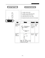
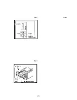
Connection
of
connector
CN 7
Check
the
connection
condition visually.
Must be
connecte
d
correctly.
Replace.
See
P.45.
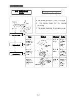
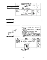
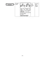
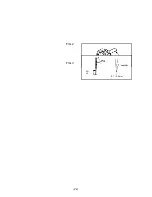
Needle bar
reciprocator
Power circuit board
Connector
①-⑥
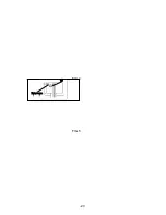
Jump lever
Needle bar
reciprocator
0.5mm
CN7
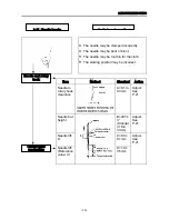
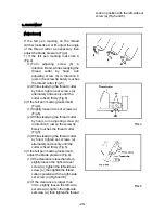
Needle bar
reciprocator
Jump motor
(pulse motor)
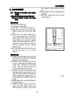
-20-
Summary of Contents for ESP9000
Page 1: ...SERVICE MANUAL Embroidery Machine ESP9000 15 needles...
Page 2: ......
Page 13: ...FIG 3 48...
Page 24: ...FIG 4 59...
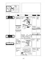
Page 36: ...Connection of connector CN 10 Must be connected correctly Replace See P 47 CN10 11...
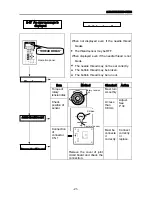
Page 40: ...Picker height C 7 9 mm when piker solenoid is ON Adjust See P 27 15...
Page 58: ...FIG 2 FIG 3 201 3 0 1 0 3 mm 22...
Page 63: ...FIG 4 e Drive arm FIG 5 27...
Page 70: ...FIG 3 34...
Page 72: ...FIG 2 FIG 3 201 3 0 1 0 3 mm 22...
Page 74: ...FIG 2 FIG 3 Needle bar Stopper Needle bar Connecting stud 24...
Page 77: ...FIG 4 e Drive arm FIG 5 27...
Page 84: ...FIG 3 34...
Page 86: ...FIG 4 31...
Page 88: ...FIG 4 33...
Page 90: ...FIG 2 35...
Page 93: ...2 a Sensor arm 3 38...
Page 95: ...FIG 3 FIG 4 VR6 Power supply board 40...
Page 97: ...FIG 3 FIG 4 0 5 to 0 8mm 0 2mm or less Hook support hook support 37...
Page 100: ...FIG 4 40...
Page 103: ...FIG 2 Needle bar c Top dead center stopper needle bar connecting stud FIG 3 43...
Page 105: ...FIG 5 45...
Page 111: ...Printed in Japan 2002 8...


