


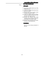

4. REPLACEMENT OF MAIN COMPONENTS
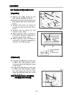
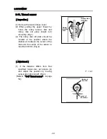
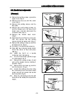
4-3. Thread catcher
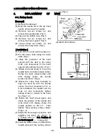
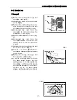
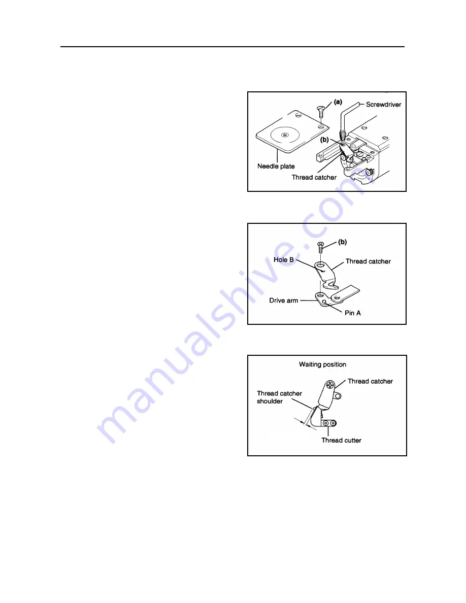
[Removal]
(1) Remove the table set.
(2) Remove two setting screws (a) and
detach the needle plate. (Fig.1)
(3) Remove set screw (b) and detach the
thread catcher. (Fig.1)
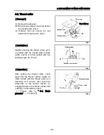
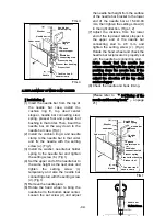
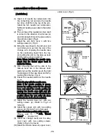
[Installation]
(1) Put hole B of the thread catcher
through pin A of the thread catcher
drive arm.
(2) Tighten setting screw (b). (Fig.2)
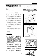
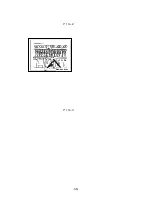
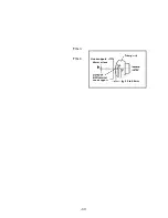
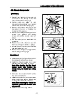
[Inspection]
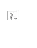
(1)
When the thread catcher is in the
standby position, the dimension
between the shoulder and the thread
cutter must be 0 ± 0.5mm. (Fig.3)
[Please refer to 『 “ 3-3 standby
position of thread catcher” 』 on page
24]
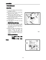
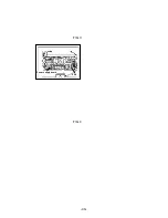
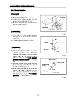
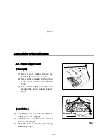
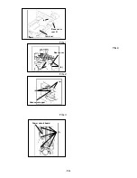
(2)
Remove the bed cover A and remove
the connecting plate from the pin of
the thread trimming lever.
(3)
Move the thread catcher by hand and
check the blade pressure of the
thread catcher and the thread cutter.
(Fig.4) [Please refer to 『“ 3-4 Blade
pressure” 』 on page 25]
FIG.1
FIG.2
0
±
0.5mm
FIG.3
-39-
Summary of Contents for ESP9000
Page 1: ...SERVICE MANUAL Embroidery Machine ESP9000 15 needles...
Page 2: ......
Page 13: ...FIG 3 48...
Page 24: ...FIG 4 59...
Page 36: ...Connection of connector CN 10 Must be connected correctly Replace See P 47 CN10 11...
Page 40: ...Picker height C 7 9 mm when piker solenoid is ON Adjust See P 27 15...
Page 58: ...FIG 2 FIG 3 201 3 0 1 0 3 mm 22...
Page 63: ...FIG 4 e Drive arm FIG 5 27...
Page 70: ...FIG 3 34...
Page 72: ...FIG 2 FIG 3 201 3 0 1 0 3 mm 22...
Page 74: ...FIG 2 FIG 3 Needle bar Stopper Needle bar Connecting stud 24...
Page 77: ...FIG 4 e Drive arm FIG 5 27...
Page 84: ...FIG 3 34...
Page 86: ...FIG 4 31...
Page 88: ...FIG 4 33...
Page 90: ...FIG 2 35...
Page 93: ...2 a Sensor arm 3 38...
Page 95: ...FIG 3 FIG 4 VR6 Power supply board 40...
Page 97: ...FIG 3 FIG 4 0 5 to 0 8mm 0 2mm or less Hook support hook support 37...
Page 100: ...FIG 4 40...
Page 103: ...FIG 2 Needle bar c Top dead center stopper needle bar connecting stud FIG 3 43...
Page 105: ...FIG 5 45...
Page 111: ...Printed in Japan 2002 8...


