background image

TOYOTA  4RUNNER 

2020 – 

DASH CAMERA

PROCEDURE  

Page 7 of 24

Issue D:  11/06/19

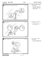
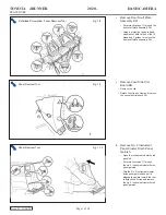
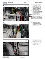
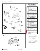
k. Remove No. 2 Instrument

Panel Cluster Finish Panel

Garnish.

• Open the instrument cluster finish

panel lid.

Put protective tape (*1) around

the No. 2 instrument cluster finish

panel garnish.

• Grip the No. 2 instrument cluster

finish panel garnish and pull it

diagonally upward toward the rear

to detach the 5 clips and remove

the No. 2 instrument cluster finish

panel garnish.

j.

Remove Cowl Side Trim

Board RH.

• Remove the clip.

Detach the clip and claw and remove

the cowl side trim board RH.

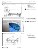
i. Remove Door Scuff Plate

Assembly RH.

Put protective tape (*1) around the

door scuff plate assembly RH.

Using a protective tape wrapped

screwdriver, detach the 4 clips, 10

claws and 2 guides to remove the

door scuff plate assembly RH.

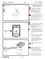
Flat Blade Screwdriver, Panel Removal Tool

Fig. 1-8

Panel Removal Tool

Fig. 1-9

*1

*1

Panel Removal Tool

Fig. 1-10

Summary of Contents for PK6A3-33HT1

Page 1: ...oval Tool Toyota SST 00002 06001 01 Side Cutters Torque Wrench Battery 48 in lbf 5 4 N m Ground Bolt 75 in lbf 8 5 N m Knee Airbag 88 5 in lbf 10 N m Pliers Needle nose Universal Scissors Tape Measure Ruler Ratchet Tape Electrical Masking Socket 10mm Extension Special Chemicals Cleaner VDC Approved Cleaner Glass Cleaner Toyota Touch Glass Cleaner Service Part s PK6A4 33HT1 Dash Camera Wire Harness...

Page 2: ... Disassembly Reassembly Electrical Component Disassembly Reassembly Use of Special Chemicals Temperature Torque Recheck Window Label Installation TPMS Check Please refer to ETAS for a copy of this document Table of Contents I Preparation 1 3 1 Table of Contents 2 2 Wire Harness Outline 3 II Procedure 4 21 1 Vehicle Disassembly 4 2 Dash Camera Installation 10 3 Wire Harness Installation 13 4 Vehicl...

Page 3: ... 24 Issue D 11 06 19 Toyota 4Runner Wire Harness Outline DC Vehicle Description A Dash Camera B 5P Blue Dash Camera connector C 5P Blue for Dash Camera D G1 Ground Terminal E F42 Red Wire Splicing Connector F F42 Yellow Wire Splicing Connector E D B C A F ...

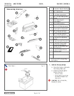
Page 4: ...Sub Assembly 11 Front No 2 Console Box Insert 12 Lower Instrument Cover LH 13 Lower No 2 Instrument Panel Airbag Assembly 14 Instrument Panel Box Door Cover 3 pcs 15 Lower Instrument Panel Sub Assembly Disconnect all Corresponding Connectors Disassembly Overview 11 7 9 8 3 10 1 12 1 Vehicle Disassembly a Place the Vehicle in Park with the Parking Brake set b Disconnect the Negative Battery Termina...

Page 5: ...tach the 2 claws and remove the front No 1 assist grip plug RH d Remove No 1 Assist Grip Remove the 2 bolts Detach the 2 claws and remove the No 1 assist grip e Remove the Front Pillar Garnish RH Detach the clip and 3 guides and remove the front pillar garnish RH Panel Removal Tool Fig 1 4 10mm Socket Fig 1 3 Panel Removal Tool Flat Blade Screwdriver Fig 1 2 1 ...

Page 6: ...ion Clip Guide g Remove Drive Monitor Switch w Drive Monitor Switch Detach the 4 claws to remove the drive monitor switch Disconnect the connector h Remove Map Light Assembly Open the cover w o Drive Monitor Switch Remove 2 screws Detach the 2 clips to remove the map light assembly Disconnect the connector Panel Removal Tool Fig 1 6 10mm Socket Panel Removal Tool Fig 1 7 Fig 1 5 Downward ...

Page 7: ...ard the rear to detach the 5 clips and remove the No 2 instrument cluster finish panel garnish j Remove Cowl Side Trim Board RH Remove the clip Detach the clip and claw and remove the cowl side trim board RH i Remove Door Scuff Plate Assembly RH Put protective tape 1 around the door scuff plate assembly RH Using a protective tape wrapped screwdriver detach the 4 clips 10 claws and 2 guides to remo...

Page 8: ...d remove the lower instrument cover LH m Remove Front No 2 Console Box Insert Detach the 2 clips and guide to remove the front No 2 console box insert l Remove No 2 Instrument Panel Under Cover Sub Assembly Detach the 3 clips and 2 guides and disconnect the connector to remove the No 2 instrument panel under cover sub assembly Panel Removal Tool Fig 1 12 Panel Removal Tool Fig 1 11 Flat Blade Scre...

Page 9: ...p the Airbag in a Blanket or the like and place it on top of a box CAUTION Prevent stress on the Airbag Harness q Remove Instrument Panel Box Door Cover HINT Use the same procedure for all 3 instrument panel box door covers Using a protective tape wrapped screwdriver 1 detach the 2 claws and 2 guides and remove the instrument panel box door cover 10mm Socket Extension Panel Removal Tool Fig 1 14 F...

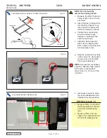
Page 10: ...1 r Remove Lower Instrument Panel Sub Assembly Remove the 3 screws and 2 bolts Detach the 10 clips and guide Remove wires for glove box lamp and remove the lower instrument panel Phillips Screwdriver 10mm Socket Panel Removal Tool Fig 1 17 Tape Measure Ruler Scissors Fig 2 2 Vinyl Sheet 2 x 25x200 mm 25mm 25mm b Cut out 2 25x200mm sized pieces from the Vinyl sheet as shown 250mm 80mm 30mm 30mm 30m...

Page 11: ...he left of the Rearview Mirror channel and mark it with Masking tape j Measure 70mm from the edge of the shade band and mark it with Masking tape NOTE Do not touch the camera lens during install c Measure the Wire Channel to 90mm length and cut to size as shown d Insert the Dash Camera Wire into the Wire Channel then insert the Wire Channel into the Dash Camera as shown e Tighten the screw making ...

Page 12: ...to attach template to the windshield n Attach the Dash Camera on the Windshield aligning it within the Dash Cam Mounting Template HINT Align camera to location shown by the template Confirm camera is parallel with mirror before fixing position Panel Removal Tool Fig 2 8 Masking Tape Fig 2 7 NOTE Be careful not to damage the Headliner NOTE To achieve maximum bond strength of adhesive the attachment...

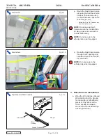
Page 13: ...h a 10mm overlap in between and secure with electrical tape closed spiral wrap Side Cutters Fig 2 10 Tape Measure Ruler Scissors Fig 3 1 Ground Wire 390mm 10mm Overlap Ground Terminal Side Cutters Fig 2 9 1 2 p Route the Dash Camera wire along and behind the vehicle harness then secure using 2 vehicle harness clips and 2 Wire Ties 1 2 Rotate the Wire Tie Ratchet away from the A pillar cover NOTE D...

Page 14: ... vehicle ground terminal and reinstall the Bolt Torque 75 in lbf 8 5 N m NOTE Place the Wire Harness Ground Terminal behind the vehi cle ground terminal at 90 degrees e Disconnect Connector F42 40P White located on the left side of the blower motor f Remove the electrical tape closest to the connector securing the wires 10mm Socket Torque Wrench Fig 3 2 d Secure both the Dash Camera wire and Groun...

Page 15: ...onnector Housing along the pleat line i Pinch the Splicing Connector s housing together until a click sound can be heard twice VERIFY Ensure locks have engaged on both sides NOTE Ensure there is no gap between the upper and lower half of the Splicing Connector locks Fig 3 5 Vehicle Wire Dash Camera Harness Wire Splicer Connector Housing Lock Engaged No Gap Fig 3 6 Click Click No Gap EX A M PLE ...

Page 16: ...4 13 12 11 10 9 8 7 4 2 1 3 24 25 26 27 28 29 30 31 32 33 34 35 36 37 38 39 40 22 23 21 5 6 Connector View from Wire Side Connector View from Wire Side Splicing Connector Splicing Connector Hinges Hinges Pliers Pliers Blue Wire Violet Wire Splicing Connector Foam Tape 30x80mm Foam Tape 63x80mm Fuse NOTE Reference steps g i for Wire Splicing Connector example l Install the Wire Harness with the Yel...

Page 17: ... Connector s Wrap the Wire Harness Male Blue Connector with 1 piece of 30x80mm sized Foam tape NOTE Prior to securing Wire Ties 7 8 apply electrical tape to the vehicle harness and dash camera wire t Secure Wire Harness with the Ground wire to the vehicle harness with 1 Wire Tie 7 u Loop the Ground Wire excess wire and route with the Dash Camera Harness along the vehicle harness and secure with 1 ...

Page 18: ... excess Ground Wire using electrical tape and secure with Dash Camera Wire Harness to the vehicle harness using 1 Wire Tie 11 as shown w Secure the Wire Harness Fuse and the excess Wire Harness to the vehicle harness using 1 Wire Tie 10 as shown Side Cutters Fig 3 13 Side Cutters Fig 3 14 7 5 9 8 10 11 ...

Page 19: ...wdriver Fig 4 2 2 1 1 Lower Instrument Panel Sub Assembly 2 Instrument Panel Box Door Cover 3 pcs 3 Lower No 2 Instrument Panel Airbag Assembly 4 Lower Instrument Cover LH 5 Front No 2 Console Box Insert 6 No 2 Instrument Panel Under Cover Sub Assembly 7 No 2 Instrument Panel Cluster Finish Panel Garnish 8 Cowl Side Trim Board RH 9 Door Scuff Plate Assembly 10 Map Light Assembly 11 Drive Motor Swi...

Page 20: ...all the No 2 Instrument Panel Under Cover Sub Assembly h Install the No 2 Instrument Panel Cluster Finish Panel Garnish i Install the Cowl Side Trim Board RH j Install the Door Scuff Plate Assembly RH k Install Map Light Assembly l Install Drive Motor Switch if equipped m Install No 1 Forward Recognition Cover n Install the Front Pillar Garnish RH Attach the clip and 3 guides to install the front ...

Page 21: ...n the bottom corner of the Dash Camera s kit box as shown w Remove the sticker from the Dash Camera box and tape to the back cover of the owners manual x Alternate process Write the password from the Dash Camera kit box on the back cover of the owners manual NOTE Password is all in capital letters aa Sealed in its protective bag Torque Wrench Fig 4 6 Fig 4 7 Fig 4 8 Write Down Password QR Code Ser...

Page 22: ...ge 22 of 24 Issue D 11 06 19 Accessory Function Checks Check Look For Vehicle Appearance Check Perform Look For After accessory installation and removal of protective cover s perform a visual inspection of the vehicle Ensure no damage including scuffs and scratches was caused during the installation process ...

Page 23: ...ate a system malfunction Tire Pressure Monitoring System TPMS Prior to TPMS activation and Pre delivery Service PDS of the Vehicle the TPMS light will blink when IG is turned on After TPMS activation and PDS of the Ve hicle the TPMS light will illuminate for a few seconds and go off when IG is turned on Air Bag Warning Light If the warning light remains on it may indicate a system malfunction Crui...

Page 24: ...ock if equipped Navigation System if equipped Audio Video if equipped USB Connections if Equipped Steering Wheel Audio Control if equipped HVAC Front Windshield Defogger if equipped Rear Window Defogger if equipped Side Mirror Defogger if equipped Accessory Power Socket if equipped Massage Seats if equipped Heated Vented Seats if equipped Glove box Light if equipped Trunk Cancel Switch if equipped...

Reviews: