background image

Celica (RHD)  -  15

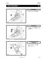
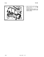
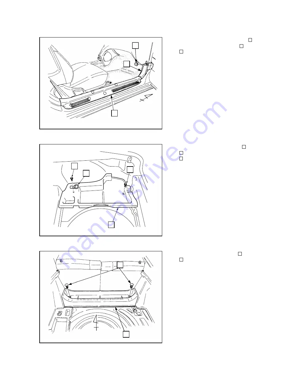
5.

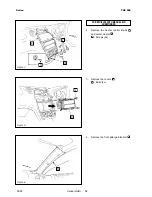
Remove the cowl side panel (RH)

and front door scuff plate (RH)

.

: Nut

12

11

10

Celica

TNS 500

Figure 7

09-99

12

11

10

6.

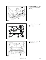
Remove the deck floor box (RH)

.

: Hook
: Bolts (2x)

5

18

19

Figure 8

19

5

5

18

7.

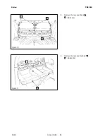
Remove the luggage front box

.

: Clips (2x)

15

14

Figure 9

14

15

Summary of Contents for TNS 500

Page 1: ...T O Y O T A N A V I G A T I O N S Y S T E M PART NUMBER NAVIGATION KIT PART N 08545 00803 TOYOTA MOTOR CORPORATION INSTALLATION INSTRUCTIONS FOR T23 R Manual Ref Nr N1RT23 0 00 ...

Page 2: ...rcibly pull any car wiring harness Rough tugging may result in opened con nections or a broken wire or harness Confirm that lamps horn wiper and other car accessories operate normally Protect your car with fender covers seat and so on Use the correct tool when tightening bolts or nuts Before drilling a hole check that the rear of the mounting wall is clear Be sure to firmly tighten connectors and ...

Page 3: ...u Ten Audio Unit with AVC LAN 10 Matsushita Audio Unit with AVC LAN 11 Audio Units with 13PIN Connector without AVC LAN 12 Vehicle Disassembly 13 Installation of the GPS Antenna 17 Wire Harness Installation 19 Installation of the Computer 25 Monitor Installation 28 Wire Harness Connection 31 Storage of the Remote Control 34 System Start Up 35 TABLE OF CONTENTS ...

Page 4: ... or TM4000 08600 00888 18401 86100 20510 or 58408 86100 60080 TF4301 08600 00922 or TM4000 08600 00888 18401 86100 20510 or 58408 86100 60080 ADD ON UNITS CD CHANGER TM0461 08601 00879 TM0461 08601 00879 NAVIGATION ASSY 08545 00803 08545 00803 08545 00803 08545 00803 NECESSARY PARTS W H 08695 00260 W H 08695 00260 REQUIRED PARTS SUBKITS ...

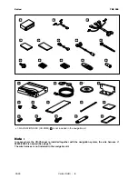
Page 5: ... Blue 2 REMOTE CONTROL 1 STORAGE BATTERY 2 13 12 11 10 9 8 7 6 5 4 3 2 1 COMPUTER 1 GPS ANTENNA 1 1 NAVIGATION DISC 1 COMPUTER BRACKET 2 SET BOLT M5 x 8 4 CORD CLAMP 6 TAPE 2 WIRE TIE 6 EARTH PLATE 1 ANCHOR BOLT 4 BOLT M5 x 16 4 BOLT M5 x 20 1 HOLD BRACKET 1 ADHESIVE TAPE 3 33 32 31 30 29 28 27 26 25 24 23 22 21 20 1 NAVIGATION DISC CD ROM is not included in the navigation kit 22 NAVIGATION SYSTEM...

Page 6: ... CD ROM is not included in the navigation kit 22 1 20 26 27 28 29 30 31 32 21 22 23 24 25 33 Note In cases where the CD Changer is installed together with the navigation system the wire harness n 08695 00260 is needed See page 7 The wire harness is not included in the navigation kit ...

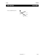
Page 7: ...09 99 Celica RHD 7 Celica TNS 500 For CD and MD Changer only 48 WIRE HARNESS 08695 00260 ...

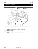
Page 8: ...ARNESS SUB ASSY SPEED LINE VIOLET WHITE WIRE HARNESS ANTENNA WIRE WIRE HARNESS REVERSE SENSOR WIRE RED BLUE INSTALLATION OVERVIEW 2 6 Audio Assembly Monitor Wire Harness 3 Computer 20 Antenna Wire to the Deck Floor Box 2 3 6 GPS Antenna 21 1 ...

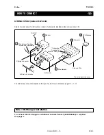
Page 9: ...Antenna 21 The wire harness connection depends on the type of audio for more details see pages 10 11 12 To connect the CD Changer an additional subwire harness 08695 00260 is required See page 7 Note CD Changer installation Audio assy Splicing connector Vehicle wire harness 12P 10P 6P 8P 1P 13P 2P 8P DIN 13P do not remove the cover HOW TO CONNECT Wire Harness Sub Assy Speed Line violet white 2 Con...

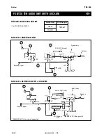
Page 10: ... Reverse signal SPD SPD Audio Unit Application AUDIO ASSY NAVIGATION SYSTEM AUDIO ASSY NAVIGATION SYSTEM CD CHANGER 2 3 20 21 1 8P 8P 6P 13P 10P 10P 12P 12P 12P 1P 2P 08695 00260 To be ordered separately 08695 00260 Disconnect To CD Changer unit 3 20 21 1 DETAILED CONNECTION OUTLINE FUJITSU TEN AUDIO UNIT WITH AVC LAN DIN 13P No use Audio Assy 2 CD Changer wire ...

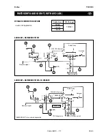
Page 11: ...RNESS WIRE HARNESS 2 6 7 7 3 20 21 1 10P 08695 00260 Connection CD Changer wire To CD Changer unit 2 3 20 21 1 6 8P 12P 12P 12P 12P 2P 13P 8P 8P 6P 10P 10P 1P 12P MATSUSHITA AUDIO UNIT WITH AVC LAN Antenna Antenna Audio Assy Reverse signal Reverse signal SPD SPD 08695 00260 To be ordered separately DIN 13P No use Audio Assy DIN 13P No use Audio Unit Application DETAILED CONNECTION OUTLINE ...

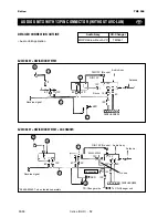
Page 12: ...P 2P 3 20 21 No use 08695 00260 12P 10P AUDIO UNITS WITH 13PIN CONNECTOR WITHOUT AVC LAN 08695 00260 To be ordered separately Audio Unit Application DETAILED CONNECTION OUTLINE AUDIO ASSY NAVIGATION SYSTEM CD CHANGER WIRE HARNESS Antenna Antenna Audio Assy Audio Assy Reverse signal Reverse signal SPD SPD 1 DIN 13P No use DIN 13P No use 1 WIRE HARNESS CD Changer wire To CD Changer unit Connection 2...

Page 13: ...ve the center cluster Screws 2x 4 6 FOR M T MODELS 1 Remove the shift knob and console panel 1 2 FOR A T MODELS 1 Remove the console panel 1 Yaris TNS 500 Celica RHD 13 VEHICLE DISASSEMBLY Figure 1 Figure 2 09 99 Celica TNS 500 1 2 1 Figure 3 6 4 ...

Page 14: ... CONDITIONER 2 Remove the heater control knobs and center cluster Screws 2x 4 6 7 3 Remove the covers Bolts 4x 4 8 4 Remove the front pillar garnish RH 9 Figure 5 Figure 6 Celica RHD 14 Celica TNS 500 Figure 4 09 99 6 4 4 7 8 4 9 ...

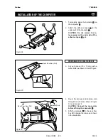
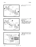
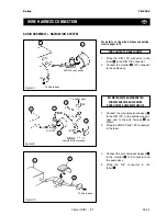
Page 15: ...wl side panel RH and front door scuff plate RH Nut 12 11 10 Celica TNS 500 Figure 7 09 99 12 11 10 6 Remove the deck floor box RH Hook Bolts 2x 5 18 19 Figure 8 19 5 5 18 7 Remove the luggage front box Clips 2x 15 14 Figure 9 14 15 ...

Page 16: ...9 Remove the rear seat cushion Hooks 2x 18 17 Figure 11 Celica RHD 16 8 Remove the rear seat back Bolts 4x 5 16 Celica TNS 500 Figure 10 09 99 5 5 16 18 17 ...

Page 17: ...ing a cutter knife cut off the weath er strip CAUTION Be careful not to dam age the antenna cord 3 Wrap the tape around the antenna cord and run the wire between the windshield and instrument panel For the cut of tape see page 20 26 26 Weather Strip yy yy yy yy yy yyy yyy 4 Wire the antenna cord to the computer along with wire harness as shown in the left figure CAUTION Tape the tip of the screw d...

Page 18: ...shown in the left figure 3 Locate and disconnect the 20P con nector from the center J B Splicing Connector Vehicle Wire Harness Pliers 20P Connector white SPEED SPD SENSOR WIRE TO MONITOR INSTALLATION 1 Take the wire harness sub assy and cut and tape the red white wire 2 1 red white Tape violet white 2 Figure 17 ...

Page 19: ...ion from the right 6 Using a splicing connector attach the wire harness sub assembly speed sensor wire violet white to the vehicle wire 7 Route the speed sensor wire violet white to the audio opening 2 2 2 Vehicle Wire Harness white red REVERSE SENSOR WIRE INSTALLATION Splicing Connector Vehicle Wire Harness Pliers Figure 19 1 Locate and disconnect the 8P connec tor black at the top of the center ...

Page 20: ...or attach the reverse sensor wire red blue to the vehicle wire 6 Figure 21 Wire Harness Side 8P Tab 8P black Vehicle Wire Harness red black 3 Splicing Connector 5 Cut the tape or into 10 equal sized pieces 26 4 Figure 22 or tape tape and tape are exactly the same tape 26 4 26 4 6 Cut one tape or into 2 equal sized pieces 26 4 Figure 23 or tape tape and tape are exactly the same tape 26 4 26 4 ...

Page 21: ...ly with the tape or 26 4 2 2 3 2 3 Figure 24 6 3 2 4 26 Tape or 26 Tape or 4 3 Route the wire harness as shown the left figure 3 Figure 25 3 yyy yyy yyy yyy yyy yyy yyy yyy yyy yyy yyy yyy yy yy yy yyy yyy yyy yy yy 4 Remove the floor carpet and route the antenna cord behind the rear seat 5 Adjust the length of the antenna cord and affix it after routing the cord to the computer procedures in 6 20...

Page 22: ... 09 99 6 Route the antenna cord securely in between the trim to the computer connection location CAUTION Route the antenna cord securely in between the trim so that it does not show 20 Figure 27 20 Antenna Cord and Wire Harness 3 ...

Page 23: ...under part of the brackets CAUTION Do not remove the re lease paper on the under side of the adhesive tapes yet 33 23 33 20 23 23 24 24 20 33 Deck Floor Box RH 15mm 15mm 4 Route the harness and antenna cord through the cut hole as shown in figure 30 and connect it CAUTION Connect the connectors before affixing the computer 5 Affix the computer to the deck floor box RH following the dimension shown...

Page 24: ...K FLOOR BOX 6 Slit the luggage carpet at the computer installation position 20 Figure 31 210mm Computer installing part 20mm 20mm 150mm 7 Install the computer at the left rear position of the luggage room 20 Figure 32 30mm 0mm 20 Slit Asphalt Seat Right Side ...

Page 25: ...io assy and 8P con nector to the monitor 1 3 1 2 3 The way to connect the splicing connector After checking the type and line color of the connector lock it Even if the hinge of the connector is broken the perfor mance does not charge Do not reuse the connector 3 2 1 Wrap the urethane tape around to hold the harness Cord color violet white 3 2 Center Brace Bracket Radio Connector 8P Connector Bild...

Page 26: ...ee Chapter Wire Harness p 27 to confirm wire harness connection to monitor and audio assembly 1 5 1 Figure 34 Figure 35 Cover Cover Audio Assembly Bracket R Bracket R Bracket L Bracket L Panel L Panel L Panel R Panel R 4 5 4 5 1 5 After connecting wire harness to moni tor and audio assembly install the monitor and audio assembly Bolts 4x 5 1 1 Figure 36 Audio Assembly 5 ...

Page 27: ... UNITS POUR UNITES AUDIO MATSUSHITA 1 Connect the wire harness sub assy to the DIN 13P to the vehicle wire har ness and to the wire harness as shown 2 Wrap the DIN 13P and 10P connectors in the foam 3 7 10P 10P Vehicle Wire Harness DIN 13P not used 12P To Audio assy 5 1 10P 7 AUDIO ASSEMBLY NAVIGATION SYSTEM Figure 37 2P Figure 38 1 5 5 3 To Audio assy DIN 13P 3 Connect the wire harness sub assy t...

Page 28: ...a CD Changer is installed in conjunction with a navigation system wire harness 08695 00260 is necessary 08695 00260 is not included in the navigation kit but to be ordered separately To Audio assy 12P 12P 1P 08695 00260 1 6 12P 5 2 Wrap the 12P connectors in the foam 5 Figure 41 To Changer wire To Audio assy FOR FUJITSU TEN AUDIO UNITS 1 Disconnect the 1P connectors To monitor 1 Disconnect 1P 12P ...

Page 29: ...Celica RHD 29 Celica TNS 500 09 99 To monitor 1 Cut 1P 1P 12P 12P 08695 00260 2 Secure the 1P connectors with wire tie 8 Figure 43 8 To Audio assy To Changer wire ...

Page 30: ...L Figure 44 Figure 45 Stick the soft part of the Velcro to the rear of the remote control 12 11 NORMAL STORAGE Attach the hard part of the Velcro to the mid console 10 HIDE AWAY STORAGE Attach the hard part of the Velcro to the inside of the glove compartment 10 10 10 11 12 ...

Page 31: ...sc Figure 47 1 Connect the battery and turn the igni tion switch to the ACC position 2 Slide the eject switch on the computer to the left to open the disc insertion slot 3 With the label side of the disc facing up insert the disc into the disc inser tion slot The disc will be pulled into the com puter automatically 4 Slide the eject switch on the computer to the right to close the disc insertion O...

Page 32: ...09 99 Celica RHD 32 Celica TNS 500 Figure 49 b The display will slide out Figure 50 3 a Raise the display by hand Figure 51 TOYOTA NAVIGATION SYSTEM b An image will appear on the screen ...

Page 33: ...s been Changed in the Navigation System Owner s Manual 6 Set the system to the customers language by following the section on language setting in the Navigation System Owner s Manual NOTE In case of any abnormality please refer to the TOYOTA Navigation System Troubleshooting Guide 7 Take the vehicle for a test drive and confirm that the map scrolls automatically REFIT THE TRIM AND REMOVED PARTS ...

Page 34: ...Celica LHD 34 Celica TNS 500 09 99 NOTES ...

Page 35: ...GENUINE PARTS ...

Reviews: