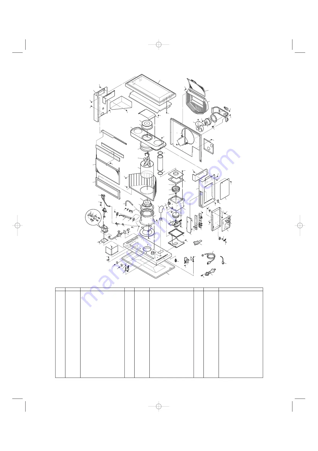
background image

REF #

PART #

PART NAME

REF #

PART #

PART NAME

REF #

PART #

PART NAME

41

40

39

76

56

57

55

64

3

4

64

64

64

29

64

45

70

60

73

63

64

68

67

19

11

64

12

19

63

64

69

34

77

75

21

16

61

38

10

1

71

64

28

26

23

22

52

53

64

64

64

64

64

64 64

49

64

25

24

27

64

31

33

20

37

36

32

63

63

74

50

44

43

42

48

35

47

51

63

46

46

64

65

65

58

62

63

6

9

30

7

2

70

59

64

63

72

54

63

66

63

64

63

63

64

8

14

15

16

18

17

13

5

78

1
2
3
4
5
6
7
8
9

10
11
12
13
14
15
16
17
18
19
20
21
22
23
24
25
26
27

28
29
30
31
32
33
34
35
36
37
38
39
40
41
42
43
44
45
46
47
48
49
50
51
52
53
54

55
56
57
58
59
60
61
62
63
64
65
66
67
68
69
70
71
72
73
74
75
76
77
78
79
80

20479946
20450007
20479570
20479929
20479960
20479963
20479970
20479964
20479931
20479903
20479972
20479940
20479944
20479945
20479955
20479981
20479909
20479908
20475877
20479942
20479943
20478026
20478383
20479518
17185580
20474921
20474920

20479911
20475194
20479937
20479947
20478871
20475883
20475875
20475878
20478534
20479919
20479941
20478550
20475551
20475552
20478512
20478378
20478379
20479983
20478306
20479976
20479901
20479917
20479914
20479915
10005597
20479952
20479969

20478373
20479891
20474925
20479935
20475071
20478366
20479987
20474059
20479956
20474050
20476482
20479958
20474051
20476452
20475554
20476454
20474053
20474055
20474057
20450120
20475874
20474272
20479957
20479885
20479996
20479998

Front panel
Plumb bob
Adjustable leg
Drip tray
Top plate
Right side panel
Access panel
Left side panel
Control panel door
Grille
Fan cover
Circulation air filter
Heat exchanger
Canopy
Canopy gasket
Glass cylinder gasket
Glass cylinder
Ceramic log
O-ring (P75)
Burner assembly
Burner ring
Fuel nozzle
Fuel nozzle gasket
Igniter
Igniter gasket
Igniter guide gasket
Igniter cover

Primary flame rod
Burner gasket
Blower motor assembly
Blower motor assembly with case
Blower motor exhaust fan
Blower motor intake fan
Blower motor case gasket
Rubber mat
Fuel sump
Fuel pump
Fuel pipe assembly
Fuel inlet strainer
Drain screw with o-ring
Strainer gasket
Main circuit board
Fuse A (10A)
Fuse B (5A)
Outlet adapter
High limit switch (=20474506)
Indicator lamp circuit
Knob for temp selector
Transformer
PCB support
PCB support (S)
Fusible link valve
Leveler fuel pipe
Circulation fan motor

Thermistor
Flue pipe
Oil catch
Power supply cord
Circulation fan
Air damper (P25)
Draft tube
Holder A
Screw AT1
Screw C
Screw B10
Screw AT2
Screw D
Screw B2
Screw 1Q
Screw B4
Screw F
Screw O
Flange Nut
Screw for igniter unit
Washer for blower motor
Screw M
Nut J
Outside nozzle gasket
Instruction manual
Carton

8

  Laser 60AT (E)  11.3.3  0:59 PM  Page 8

Summary of Contents for Laser 60AT

Page 1: ...Features SECTION B Safety Tips for Operation SECTION C Fuel Guide SECTION D Operating Controls and Part Names SECTION E Operation Before Ignition Operation Turning Heater Off SECTION F Routine Mainten...

Page 2: ...l Oil or ASTM D975 Ultra Low Sulfur Diesel ULSD 30 24 19 76 0 60 8 48 3 cm 77 lbs 35 kg Empty 2 3 4 3 diameter 7 0 7 5 cm 10 ft 3 m 3 bends or less 120 Volts AC 60 Hz Preheat 280W Burning 60W 1250 squ...

Page 3: ...prevent fire Power Failure Recovery System If power fails during heater operation heater will turn off When power resumes heater will automatically reignite to maintain the selected room temperature...

Page 4: ...Ultra Low Sulfur Diesel ULSD NEVER USE GASOLINE Use of gasoline can lead to uncontrollable flames resulting in destructive fire 1 Due to high surface temperatures keep heater away from children furnit...

Page 5: ...cause Use of a highly volatile flammable fuel such as gasoline can produce uncontrollable flames creating a severe fire hazard Note The fluidity of Ultra Low Sulfur Diesel becomes worse at temperature...

Page 6: ...K SET CLOCK TEMP START SET BACK 50 10 70 21 90 F 32 C END SET BACK SET BACK NORMAL AUTO AM PM HOUR AUTO 8 ON OFF lamp 10 Normal temper ature lamp 1 ON OFF switch 5 Timer selector 3 Temperature selecto...

Page 7: ...heating room up quickly and low or medi umcapacity warm air flow during low or medium combustion for maintaining comfortable room temperature Constantly senses room temperature and supplies informatio...

Page 8: ...20479956 20474050 20476482 20479958 20474051 20476452 20475554 20476454 20474053 20474055 20474057 20450120 20475874 20474272 20479957 20479885 20479996 20479998 Front panel Plumb bob Adjustable leg...

Page 9: ...t output will however be automatically adjusted in accordance with the room temperature registered by the temperature sensor Operation of Laser Heater can be controlled manually by the user MANUAL ope...

Page 10: ...e selector to set the room temperature desired The temperature control should be set at the position you find most comfortable Note Desired temperature setting will be displayed on the digital indicat...

Page 11: ...selector and SET BACK temperature selector at the position you desire Ex NORMAL 75 F SET BACK 60 F Note The temperature setting currently being used is displayed on the digital indicator To view and...

Page 12: ...isconnected during electrical storms Note Heater may also be shut down by lowering the setting on the temp selec tor thermostat s because heater goes into OFF cycle SECTION F ROUTINE MAINTENANCE Impor...

Page 13: ...ainer and wash with kerosene e Return the strainer to its original position Replace strainer cover and screw to secure f Wipe away any spilled fuel g Open the valve s of separate fuel tank Check for f...

Page 14: ...Normal Occasional yellow flickering in blue flame Normal When heater is started or extinguished When heater is in operation CONDITION REASON SECTION G TROUBLESHOOTING NOTE BEFORE REQUESTING FOR REPAI...

Page 15: ...our dealer Consult your dealer EE10 DOES NOT EXTINGUISH Possibly excess fuel in burner Flame sensor malfunction Consult your dealer Consult your dealer ODOR Leaking flue pipe Fuel leakage Faulty packi...

Page 16: ...ur heater needs any service or repair now is the time to call your dealer and get it done before storage That way your heater will be ready for immediate use when the next heating season begins 3 If y...

Page 17: ...installation parts are enclosed with heater For alternate installation methods you may need to purchase additional accessories which are available from your TOYOSTOVE dealer See Accessory Parts page...

Page 18: ...ap 1 PART 20474949 Screw 4G 3 PART 20474985 Oil Catch 1 PART 20474925 Inlet Hose 1 PART 20474951 Spacer 1 PART 20478967 Screw M 3 PART 20474272 Bent Joint 1 PART 20474984 L Shaped Hose 2 PART 20474975...

Page 19: ...er and flue pipe locations and fueling system consult your TOYOSTOVE dealer to purchase the necessary accessory parts Important Use only genuine TOYOSTOVE parts for your heater Use of unauthorized gen...

Page 20: ...r Pipe Support Hardware L Shaped Exhaust Joint 1 1 1 2 2 3 sets 1 NOTE Use L shaped Exhaust Joint if necessary INSTALLATION WITH EXTENSION PIPE KIT L Adjustable Exhaust Pipe Insulation cloth cover Exh...

Page 21: ...it S PART 20479896 No Name of Part Q ty 1 2 3 4 5 6 Adjustable Exhaust Pipe Max 19 11 16 Min 12 5 8 Intake Pipe 20 inch Insulating cloth cover 40 inch Pipe Holder Pipe Support Hardware L Shaped Exhaus...

Page 22: ...in your wall for the flue pipe make sure the area is free of electrical wires gas pipes and other obstacles 4 Do not install flue pipe where it will be exposed to heavy snow collected leaves or strong...

Page 23: ...e Fig 2 3 CAUTION The standard flue pipe installation as shown in Fig 2 is for wall thickness from 4 in to 9 in ONLY Note For wall thickness more than 9 in refer to page 18 for available flue pipe ext...

Page 24: ...the heat exchanger c Gently insert the ceramic logs into three 3 brackets inside of burner properly After inserting the ceramic logs install log supporter on the upper holes of the ceramic logs Adjus...

Page 25: ...inside the room Use a 2 3 4 to 3 diameter hole saw attached to an electric drill See Fig 5 The opening on the inside wall should be slightly higher than the outside opening approximately 1 4 so that...

Page 26: ...ugh the hole Secure the outer flue pipe to the wall by turning it clockwise This locks the two halves together See fig 9 IMPORTANT Make sure the arrow on the outer flue pipe flange is pointing up Make...

Page 27: ...ater Make sure the caps fit tightly onto the opening See Fig 10 NOTE If the inlet hose is not smoothly inserted into the L shaped hose apply water or soap suds to the inlet hose 8 Move the heater into...

Page 28: ...exhaust outlet opening by sliding the pipe stopper in the exhaust opening bracket See Fig 12 10 Make sure the position of the heater is level by using the plumb bob located at the right side of the he...

Page 29: ...heater a Self Adhesive Tape Peel off the protective tape on the back of the sensor and expose the adhesives Place the sensor on the desired location on the wall and press down b Wood Screw Screw down...

Page 30: ...ine and connected the tank as illustrated on page 30 NOTE An additional shut off valve installed next to the exterior wall will minimize fuel to be drained should heater have to be disconnected If the...

Page 31: ...er 60AT Fuel filter 8 1 2 ft maximum 16 in minimum Tank Vent Outdoor Fuel Tank Shut off Valve Loop 3 8 in OD Copper Tubing Shut off Valve Fusible link valve inside 31 Laser 60AT E 11 3 3 0 59 PM Page...

Page 32: ...bill of sale or credit card charge receipt or other documents evidencing the date of the Product s delivery if service is not available locally please contact our CUSTOMER RELATIONS DEPARTMENT at TOYO...

Reviews: