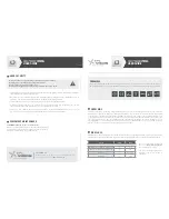
connection
User gUide
M8
3 male points
+ 24 V
1
3
4
Ground
Strobe
STROBE MODE
CONNECTION
+ 24 V
1
3
4
Ground
CONTINUOUS MODE
CONNECTION
FRONT VIEW OF THE PRODUCT’S CONNECTOR
3
4
black
1
brown
+ LED
blue
- LED
STROBE
Automate
P2/4
P3/4
During the set up, the light has to be switched off and
unplugged. Please use the fixing holes designed for
that purpose (see scheme above).
We recommend the using of M3 screws (not supplied)
with a tightening torque from 0.5 to 1.5 Nm.
We also recommend the use of a threadlocker (not sup-
plied) to avoid any risk of loosening.
timetable
dimming
strobe mode
0
20%
40%
60%
80%
100%
0%
1
2
3
4
5
6
VOLTS
Entrée Déclenchement
Sortie Éclairage
Triggering input
Light
+5V or +24V
Toward STROBE
input
From camera
/automate
+5V or +24V
From camera
/automate
0V
Toward STROBE
input
Resistance value
to be adapted
to the automaton.
Max. 4.7 kΩ
PnP-like aUtomaton oUtPUt
nPn-like aUtomaton oUtPUt
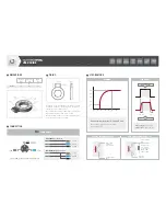
Potential dimming between 1.5 and 5 Volts.
Above 5 Volts, the product reaches 100%
of its lighting power.
Power supply : 24V +/-10%
Strobe input : 24V or 5V TTL
1.5 ms
1 ms
fixing
dimensions
Internal ø
(mm)
External ø
(mm)
Width
(mm)
A
B
C
HPRING
58
112
28


