Product Code: PROTL500A
Made in China to TQB Brands Pty Ltd specifications
Page 4
Visit us at www.tqbbrands.com.au
ASSEMBLY, OPERATION, PREVENTITIVE MAINTENANCE
1.
FEATURES
This TQ Pro 2-Stage Air/Hydraulic Telescopic Transmission Lifter offers a wide range of versatility designed to help increase
workshop productivity. For use with car and light truck transmissions. The universal mounting head provides a wide four way
tilt range and the wide base is enhanced by four heavy-duty steel swivel castors for safer manoeuvring around the workshop.
This Transmission Lifter is equipped with an air operated hydraulic system with smooth hydraulic lift and descent. The fast lift
foot operated pump and release valve keep the mechanic’s hands free during use. The height and cradle adjustability of this
telescopic Transmission Lifter makes it great for any transmission installation or removal.
2.
ASSEMBLY
Unpack the product and check contents with the exploded drawing and the parts list. Should there be any damaged or missing
parts, contact your place of purchase immediately.
1.
Attach the two leg assemblies (43) to the hydraulic main body (30) using bolts (50), washers (49), lock washers (48).
2.
Fit the 4 castors (47,52) to the legs using washers (45), lock washers (46) & nuts (44).
3.
Screw the cradle kit (51) onto the top of the lift ram rod, then assemble the adaptor as per the exploded drawing.
3.
BEFORE USE
Prior to use conduct a visual inspection checking for abnormal conditions, such as cracked welds, leaks, and damaged, loose,
or missing parts.
1.
Following assembly and before first use, loosen the Air Vent Screw (26) then leave the Transmission Lifter for one hour
to allow the hydraulic oil to settle before bleeding the system.
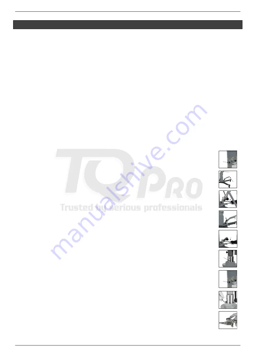
Bleeding Instructions
2.
Remove the Oil Filler Bung/Breather and if required, top up with *32 Grade hydraulic oil until the oil is
lapping the bottom of the Oil Filler Hole then replace the Oil Filler Bung/Breather.
3.
Start with the Pump Pedal Assembly in the raised position.
4.
Depress the Pump Pedal to full stroke and hold in that position. With a Hex key undo the Pump Bleed
Screw 1 full turn counter-clockwise, aerated oil will begin to exit the Pump Bleed screw housing until a
clear stream of oil with no air bubbles flows from the Pump Bleed Screw housing.
5.
Tighten the Pump Bleed Screw and raise the Pump Pedal to fully raised position, repeat instructions 1 to
4 until no air bubbles appear in the oil stream at the bleeder housing.
At this stage, the Pedal Pump Assembly should be clear of air.
In the next steps the Lift Ram assembly bleeding procedure is described
6.
Start with the Pump Pedal Assembly in the raised position.
7.
With an Allen key undo the Lift Ram Bleed Screw 1 full turn counter clockwise, aerated oil will begin to
exit the Lift Ram Bleed Screw housing until a clear stream of oil with no air bubbles flows.
8.
Tighten the Lift Ram Bleed Screw and raise the Pump Pedal to fully raised position.
9.
Repeat instructions 6 to 8 until no air bubbles appear in the oil stream at the bleeder housing and tighten
the Lift Ram Bleed Screw.
10.
Recheck the oil level as described in step 1 and top up to correct oil level if required.
At this point both the Pump and Lift Ram should be free of air.
Air Motor Pump Bleeding Instructions
11.
With the lift ram in the fully lowered position, use an Allen key to undo the Lift Ram bleed screw 1 full turn
anticlockwise.
12.
Connect the air supply to the air motor trigger assembly and hold the air motor trigger open for a minimum of 10
seconds , aerated oil will begin to exit the bleed screw housing until a clear stream of oil with no air bubbles flows.
13.
While holding the Air Motor trigger open Tighten the pump bleed screw and release the trigger.
14.
Recheck the oil level as described in step 1 and top up to correct oil level if required.
At this point the Manual Pump, Air Motor Pump and Lift Ram should be free of air
and the Lifter ready for operation
.
Oil Filler
Bung/Breather
Pump Pedal
Assembly
Hex
Key
Pump Pedal
Assembly
Pump Pedal
Assembly
Pump
Bleed
Screw
Pump Pedal
Assembly
Lift Ram
Bleed
Screw
Oil Filler
Bung/Breather
Lift Ram


