User's Manual l MBa8MPxL UM 0100 l © 2022, TQ-Systems GmbH
Page 4
2.
BRIEF DESCRIPTION
This User's Manual describes the hardware of the MBa8MPxL as of revision 02xx and 03xx.
The MBa8MPxL is designed as a carrier board for the TQMa8MPxL. The TQMa8MPxL is directly soldered on the MBa8MPxL.
Core of the MBa8MPxL is the TQMa8MPxL with an NXP i.MX 8M Plus CPU based on a Dual or Quad Cortex
®
-A53.
The TQMa8MPxL connects all peripheral components. In addition to the standard communication interfaces such as USB,
Ethernet, SD card, etc., most other available TQMa8MPxL signals are routed on 50 mil pin headers on the MBa8MPxL.
CPU features and interface can be evaluated, software development for a TQMa8MPxL-based project can start immediately.
Currently four i.MX 8M Plus derivatives are supported:
1)
i.MX 8M Plus Dual (Dual Cortex
®
-A53)
2)
i.MX 8M Plus Quad 4 Lite (Quad Cortex
®
-A53)
3)
i.MX 8M Plus Quad 6 Video (Quad Cortex
®
-A53)
4)
i.MX 8M Plus Quad 8 ML/AI (Quad Cortex
®
-A53)
2.1
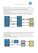
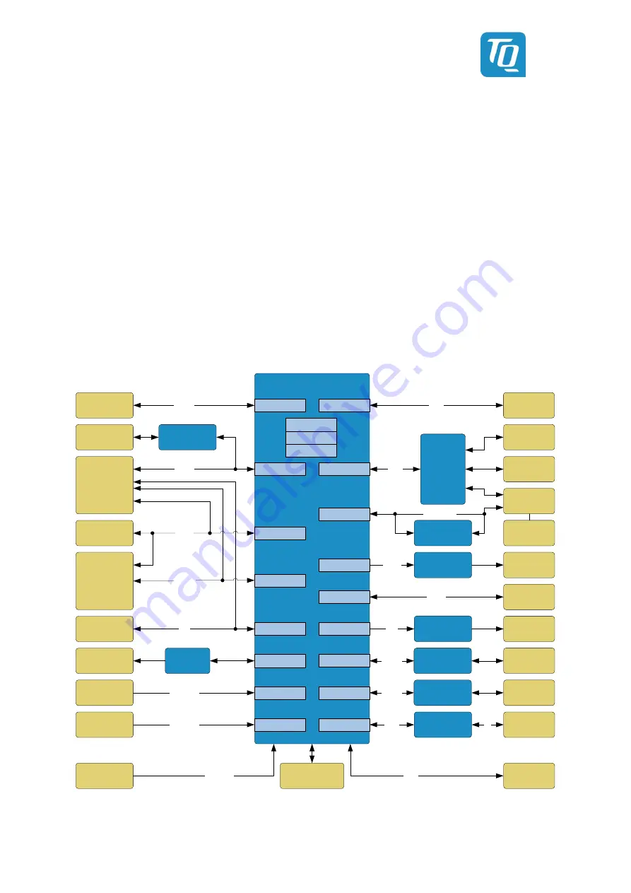
MBa8MPxL block diagram
TQMa8MPxL
(LGA-Modul)
Ethernet
10/100/1k
ENET TSN
SD-Card
uSDHC2
SDHC
MIPI DSI
MIPI CSI1
MIPI-CSI1
I2C
SAI #3
USB OTG
Boot
RAM
Power
Supply
PCIe M2-
Slot
RGMII
PCIe Data
Boot
Config
USB Hub
USB3.0 #2
USB
2x USB3.0
Touch
(LVDS)
Temp.
Sensor
I2C
Button/
LED/ FAN
GPIO
3x 3,5 mm
jack
Audio
Codec
DSI
MIPI-CSI
GPIO
V_5V_IN
DSI-to-eDP
Converter
Display-
port
Gigabit ETH
PHY
NOR Flash
E-MMC
HDMI
USB
MIPI CSI2
MIPI-CSI
LVDS
LVDS
UART
50 mil
headers
MIPI-CSI2
Mirco-USB
USB3.0 #1
PCIe
HDMI
LVDS
CAN
ENET QOS
CAN FD
CAN
Ethernet
10/100/1k
RGMII
Gigabit ETH
PHY
2x CAN
Transceiver
Bustrenner
& FTDI-Chip
2x
Micro-SIM
PCIe
RefClock
HDMI signal
conditioning
HDMI
UART
ECSPI
ECSPI
Module
Power Rails
3,5 mm
IO conn.
(Analog In,
Digital In,
Digital Out)
Figure 1:
Block diagram MBa8MPxL


