background image


User's Manual  l  MBa8MPxL UM 0100  l  © 2022, TQ-Systems GmbH 


Page  5 


2.2


MBa8MPxL interfaces, overview 

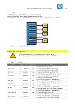
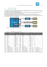
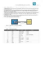
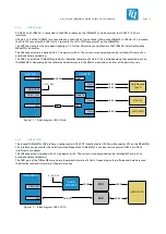
The following interfaces/functions and user interfaces are available on the MBa8MPxL: 
 

Table 2: 

Data interfaces 

Interface 

Connector 

Type 

Remark 

Audio 

X15, X16, 

X17 

3 × 3.5 mm jack 

MIC (mono), Line-in (stereo), Line-out (stereo) 

CAN FD 

X18, X19 

MC 1,5/ 3-G-3,5 

X18: CAN0 | X19: CAN1 

eDP / DP 

X65 

DisplayPort 

DSI-to-DP bridge 

Eth 1000 Base-T 

X66 

Double RJ45 

Gigabit PHY DP83867 and socket with integrated 
transformers 

GPIO / ADC 

X555 

DMC 1,5/15-G1F-3,5-LR 
P20THR 

Connected to IO bank, usage up to 24 V (GPIO) 

HDMI 

X44 

HDMI 

– 

I

2

X61 

40-pin, 50 mil pin header 

4 × I

2

JTAG 

X22 

10-pin, 50 mil pin header 

JTAG 

LVDS CMD 

X7 

20-pin, DF19G 

ZIF con USB 2.0 

LVDS Data 

X11 

30-pin, DF19G 

ZIF connector 

MIPI CSI 

X57 

60-pin, 0.8 mm, TE 
Connectivity 

CSI1 and CSI2 

PCIe / M.2 

X48 

M.2 

PCIe + USB 2.0 

SIM card 

X46 

SIM card holder 

SIM card slot 

SD card 

X42 

USDHC2 

Optional boot source and supply of module 

USB 3.0 

X36 

Stacked Type A 

USB 3.0 H1, top, USB 3.0 H2, bot 

USB 3.0 OTG 

X29 

USB1-Interface at USB Micro-B  USB OTG or Serial Download Mode 

USB Debug 

X28 

UART3, UART4 

Via FTDI chip to micro USB AB socket 


The MBa8MPxL provides the following diagnostic and user interfaces: 
 

Table 3: 

Diagnostic and user interfaces 

Interface 

Reference 

Component 

Remark 

Status LEDs 

1 × Red LED 

Reset 

7 × Green LED 

Voltages on MBa8MPxL 

2 × Green LED 

General purpose LEDs 

3 × Orange LED 

V_3V3_MOD, V_3V3_SD, V_1V8_MOD 

1 × Yellow LED 

General purpose LED 

Temperature sensor 

D1 

1 × SE97BTP 

Digital I

2

C temperature sensor 

Power / Reset 

S7 
S8 
S9 

3 × Pushbutton 

Reset 
PMIC reset 
CPU-ON/OFF 

GP button 

S12, S13 

2 × Pushbutton 

General purpose pushbuttons 

Boot-Mode 

S1 

1 × 4-fold DIP switch 

Boot Device selection 

Coin cell 

X56 

1 × battery socket 

Standard CR2032, RTC buffer 


Summary of Contents for MBa8MPxL

Page 1: ...MBa8MPxL User s Manual MBa8MPxL UM 0100 04 08 2022...

Page 2: ...backup 10 3 1 5 Temperature sensor 10 3 1 6 Fan 10 3 1 7 Reset 11 3 2 Power supply 12 3 2 1 Protective circuitry 12 3 3 Communication interfaces 13 3 3 1 Ethernet 1000 Base T RGMII 13 3 3 2 SD card in...

Page 3: ...rsonal security 33 7 CLIMATIC AND OPERATIONAL CONDITIONS 33 7 1 Protection against external effects 33 7 2 Reliability and service life 33 8 ENVIRONMENT PROTECTION 34 8 1 RoHS 34 8 2 WEEE 34 8 3 REACH...

Page 4: ...12 Pinout DisplayPort X65 18 Table 13 Pinout MIPI CSI X57 19 Table 14 Pinout LVDS data X11 20 Table 15 Pinout LVDS control X7 20 Table 16 Pinout HDMI connector X44 21 Table 17 Pinout CAN FD connectors...

Page 5: ...Block diagram SD card interface MBa8MPxL 14 Figure 11 Block diagram USB 3 0 Hub 15 Figure 12 Block diagram USB 3 0 OTG 15 Figure 13 Block diagram PCIe M 2 16 Figure 14 Block diagram UARTs 17 Figure 15...

Page 6: ...z First edition 0002 16 03 2021 Petz All Figure 1 Table 2 Table 22 Table 23 Table 24 5 1 Figure 24 Non functional changes expressions phrases Updated 3 3 V for X555 removed Level and Dir for 1 8 V 3 3...

Page 7: ...d and trademarks are rightly protected by a third party 1 3 Disclaimer TQ Systems GmbH does not guarantee that the information in this Preliminary User s Manual is up to date correct complete or of go...

Page 8: ...sed This symbol represents important details or aspects for working with TQ products Command A font with fixed width is used to denote commands file names or menu items 1 7 Handling and ESD tips Gener...

Page 9: ...omponents used for example CompactFlash cards are to be taken note of They contain if applicable additional information that must be taken note of for safe and reliable operation These documents are s...

Page 10: ...are supported 1 i MX 8M Plus Dual Dual Cortex A53 2 i MX 8M Plus Quad 4 Lite Quad Cortex A53 3 i MX 8M Plus Quad 6 Video Quad Cortex A53 4 i MX 8M Plus Quad 8 ML AI Quad Cortex A53 2 1 MBa8MPxL block...

Page 11: ...8 mm TE Connectivity CSI1 and CSI2 PCIe M 2 X48 M 2 PCIe USB 2 0 SIM card X46 SIM card holder SIM card slot SD card X42 USDHC2 Optional boot source and supply of module USB 3 0 X36 Stacked Type A USB...

Page 12: ...User s Manual l MBa8MPxL UM 0100 l 2022 TQ Systems GmbH Page 6 2 3 MBa8MPxL interfaces location Figure 2 MBa8MPxL interfaces top...

Page 13: ...User s Manual l MBa8MPxL UM 0100 l 2022 TQ Systems GmbH Page 7 2 3 MBa8MPxL interfaces continued Figure 3 MBa8MPxL interfaces bottom...

Page 14: ...lution Further information can be found in the TQMa8MPxL User s Manual On the MBa8MPxL the standard interfaces like USB Ethernet etc provided by the TQMa8MPxL are routed to industry standard connector...

Page 15: ...I2C4 Level shifter 3V3 3V3 HDMI signal conditioning chip 1V8 NP N P NP Figure 5 Block diagram I2 C bus The following table shows the addresses used on the TQMa8MPxL and the MBa8MPxL Table 4 I2 C devic...

Page 16: ...tions are documented in the MBa8MPxL schematics The temperature sensor D1 is located on the top side of the MBa8MPxL see Figure 2 Table 5 Temperature sensor SE97BTP D1 Manufacturer Device Resolution A...

Page 17: ...drain output low active Activates RESET of MBa8MPxL components Requires pull up on carrier board max 6 5 V RESET_3V3 O MBa8MPxL High Generated on MBa8MPxL from RESET_OUT IMX_ONOFF I MBa8MPxL High ON...

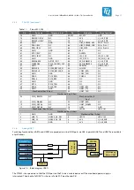
Page 18: ...heoretically possible power consumption results from the standard compliant supply of the USB PCIe M 2 and LVDS interfaces as well as from the power available at the pin headers V_24V max 6 6 A V_5V_M...

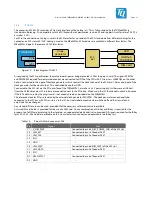
Page 19: ...event signals of ENET1 can be used via assembly option TQMa8MPxL RJ45 ENET_TSN RGMII0 ENET_QOS RGMII1 PHY 1 DP83867 PHY 2 DP83867 RJ45 EVENT1 EVENT2 SAI2 Pin header Figure 9 Block diagram Ethernet 10...

Page 20: ...nd SD UHS 1 Speed Mode SDR104 with theoretically max 104 MB s are supported UHS 1 Speed Modes SDR12 SDR25 SDR50 and DDR50 are theoretically supported but not verified The TQMa8MPxL sets USDHC2 is to 1...

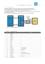
Page 21: ...ending on the software and hardware used the effective read and write rates of the ports may vary TUSB8041 TQMa8MPxL LVDS CMD USB USB Host 4 PCIe M 2 Host 3 Host 1 Host 2 USB 3 0 USB Stacked Type A US...

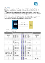
Page 22: ...e the PCIe interface of the TQMa8MPxL as well as a 3 3 V power supply Furthermore a USB host from the USB hub and an I2C interface are connected next to the PCIe lane When using the I2C functionality...

Page 23: ...PER 0 PCIE_RXP 42 NC NC 39 GND GND 40 NC NC 37 PET 0 PCIE_TXN 38 NC NC 35 PET 0 PCIE_TXP 36 UART_RTS NC 33 GND GND 34 UART_CTS NC Mechanical Key E Key 32 UART_TXD NC Mechanical Key E Key 23 SDIO_RESE...

Page 24: ...aximum of 500 mA This current must be subtracted from the current budget of the LM25119 The TC9595 s reference clock is generated by a 26 MHz oscillator which is connected to the REFCLK input TC9595XB...

Page 25: ...is not assembled by default 5 V are provided at pins 56 58 and 60 This voltage may be loaded with a maximum of 300 mA TQMa8MPxL MIPI_CSI0 MIPI_CSI1 TQ Camera Adapter 5 V 300 mA 2x CSI_I2C ECSPI1 TRIGG...

Page 26: ...port 4 of the USB 3 0 hub RESET BLT_EN PWR_EN CONTRAST PWM TQMa8MPxL LVDS0 CH0 CH1 LVDS Data USB LVDS Control 5 V 3 3 V GPIO3_IO14 GPIO3_IO 19 21 5 V 12 V USB 3 0 Hub Figure 17 Block diagram LVDS Tab...

Page 27: ...pacitors between the module and the connector according to the EARC specification TQMa8MPxL HDMI HDMI socket HDMI signal conditioning Figure 18 Block diagram HDMI Table 16 Pinout HDMI connector X44 Pi...

Page 28: ...CAN interfaces can each be terminated with a DIP switch Galv Isolation TQMa8MPxL CAN0 CAN1 3 pin shrouded header 3 pin shrouded header CAN Transceiver CAN Transceiver Figure 19 Block diagram CAN FD in...

Page 29: ...output by replacement of resistors R77 78 to R79 80 TQMA8MPxL SAI3 I2C2 Audio Codec TLV320 3 5 mm Jack 3 5 mm Jack 3 5 mm Jack MIC Line Out Line In Figure 20 Block diagram audio interface Table 18 Pi...

Page 30: ...gurable buttons see chapter 3 4 2 Alternatively both signals can be connected to a pin header All three signals use I2 C or UART pins of the i MX 8M Plus and have 3 3 V level 3 3 16 PWM The TQMa8MPxL...

Page 31: ...I3 interface of the TQMa8MPxL RESET BLT_EN PWR_EN CONTRAST PWM TQMa8MPxL IO connector ECSPI3 High Side Switch V_24V_OUT GPIO1_IO 00 01 GPIO1_IO03 GPIO1_IO 06 07 GPIO1_IO09 GPIO1_IO 14 15 4x D_Out V_24...

Page 32: ...in the following table All complete listing of all available signals can be found in Table 22 and Table 23 Table 21 Signals with IO functionality CPU pin name Signal Alternative Power group USDHC1_DA...

Page 33: ...SS0 1 NAND 1 8 V O 29 30 GND Power Ground 31 32 ISO_7816_CLK TQMa8MPxL 3 3 V I Ground Power GND 33 34 ISO_7816_RST TQMa8MPxL 3 3 V I I O V_SAI2_SAI3 GPIO SPDIF_EXT_CLK1 35 36 ISO_7816_IO1 TQMa8MPxL 3...

Page 34: ...from eMMC USDHC3 0 0 1 1 Boot from SD card USDHC2 0 1 0 x Boot from NAND not supported 0 1 1 0 Boot from QSPI 3 Byte Read 0 1 1 1 Boot from Hyperflash 3 3 V QSPI 1 0 0 0 Boot from eCSPI not supported...

Page 35: ...L is active V5 Green Status 12 V MBa8MPxL lit when 12 V for MBa8MPxL is active V6 Green Status 5 V MBa8MPxL lit when 5 V for MBa8MPxL is active V7 Green Status 3 3 V MBa8MPxL lit when 3 3 V for MBa8MP...

Page 36: ...TDO JTAG_TMS Figure 23 Block diagram JTAG The following table shows the JTAG connector pinout Table 26 Pinout JTAG pin header X22 Pin Signal Remark 1 Vref VCC 3 3 V optional 1 8 V 2 JTAG_TMS 10 k PU N...

Page 37: ...t 5 3 Housing The form factor and the mounting holes of the MBa8MPxL are designed for installation in a standard EURO housing 5 4 Thermal management The combination of MBa8MPxL and TQMa8MPxL has a pow...

Page 38: ...5 Assembly Figure 25 MBa8MPxL component placement top Figure 26 MBa8MPxL component placement bot The labels on the MBa8MPxL show the following information Table 27 Labels on MBa8MPxL Label Content AK...

Page 39: ...nsing Attention TQMa8MPxL heat dissipation The i MX 8M Plus belongs to a performance category in which a cooling system is essential It is the user s sole responsibility to define a suitable heat sink...

Page 40: ...is therefore no classification as dangerous goods Basic lithium content per cell not more than 1 grams except for lithium ion and lithium polymer cells for which a lithium content of not more than 1 5...

Page 41: ...SPI enhanced Capability Serial Peripheral Interface eDP embedded DisplayPort EEPROM Electrically Erasable Programmable Read Only Memory EMC Electromagnetic Compatibility eMMC embedded Multimedia Card...

Page 42: ...Pull Up PWM Pulse Width Modulation QSPI Quad Serial Peripheral Interface REACH Registration Evaluation Authorisation and restriction of Chemicals RGMII Reduced Gigabit Media Independent Interface RJ45...

Page 43: ...documents No Name Rev Date Company 1 i MX 8M Plus Applications Processor Data Sheet Rev 1 08 2021 NXP 2 i MX 8M Plus Applications Processor Reference Manual Rev 1 03 2021 NXP 3 Mask Set Errata i MX 8M...

Page 44: ...TQ Systems GmbH M hlstra e 2 l Gut Delling l 82229 Seefeld Info TQ Group TQ Group...

Reviews: