User's Manual l MBa8MPxL UM 0100 l © 2022, TQ-Systems GmbH
Page 25
3.3.19
IO extension
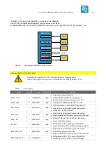
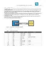
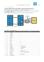
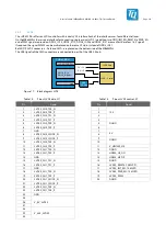
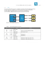
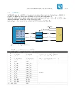
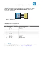
The TQMa8MPxL provides eight GPIO1 interface pins as four outputs and four inputs at an IO connector on the MBa8MPxL.
All signals can operate at up to 24 V. The corresponding circuitry is provided on the MBa8MPxL.
The high-side switches, which supply the output signals, must be supplied with 24 V (max. 2 A) at pins B3 and B4. The supply
voltage of 24 V provided at pins B1 and B2 can be used for this purpose.
Analog voltages are AD converted and transmitted to the ECSPI3 interface of the TQMa8MPxL.
RESET, BLT_EN,
PWR_EN,
CONTRAST/PWM
TQMa8MPxL
IO
connector
ECSPI3
High Side
Switch
V_24V_OUT
GPIO1_IO[00:01]
GPIO1_IO03
GPIO1_IO[06:07]
GPIO1_IO09
GPIO1_IO[14:15]
4x D_Out
V_24V_HSS_IN
ADC
2x A_In
4x D_In
Comparator
4x D_Out
4x D_In
Figure 21: Block diagram IO extension
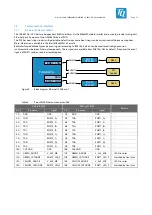
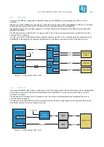
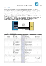
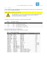
Table 19:
Pinout IO extension connector, X555
Pin
Pin Name
Signal
Remark
B1
V_24V_OUT
V_24V_OUT
Loop-through supply voltage V_24V_IN
B2
B3
V_24V_HSS_IN
V_24V_HSS_IN
Voltage supply for high-side switches (24 V)
B4
B5
GND
GND
–
B6
D_OUT2
GPIO1_IO01
0 V to 24 V
B7
D_OUT1
GPIO1_IO00
B8
D_OUT4
GPIO1_IO06
B9
D_OUT3
GPIO1_IO03
B10
D_IN1
GPIO1_IO07
B11
D_IN2
GPIO1_IO09
B12
D_IN3
GPIO1_IO14
B13
D_IN4
GPIO1_IO15
B14
ADC_IN1
ECSPI3
B15
ADC_IN2
ECSPI3
A1…A15
GND
GND
–

