User's Manual l MBa8MPxL UM 0100 l © 2022, TQ-Systems GmbH
Page 28
3.4
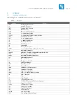
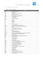
Diagnostic and user interfaces
3.4.1
Boot Mode configuration
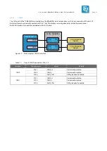
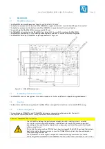
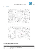
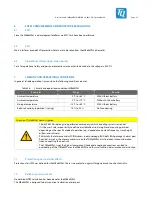
The Boot Mode is set with the 4-fold DIP switch S1 at the four i.MX 8M Plus pins Boot_Mode[3:0].
Information on the boot configuration of the i.MX 8M Plus can be found in the i.MX 8M Plus documentation; see Table 31.
Table 24:
Boot Source options TQMa8MPxL
Boot Mode[3:0]
Boot Source
0 0 0 0
Boot from eFuses
0 0 0 1
USB Serial Downloader
0 0 1 0
Boot from eMMC (USDHC3)
0 0 1 1
Boot from SD card (USDHC2)
0 1 0 x
Boot from NAND (not supported)
0 1 1 0
Boot from QSPI (3-Byte Read)
0 1 1 1
Boot from Hyperflash 3.3 V (QSPI)
1 0 0 0
Boot from eCSPI (not supported)
3.4.2
Push buttons
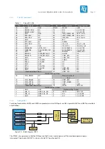
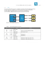
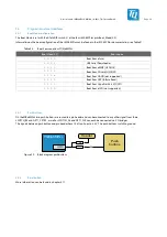
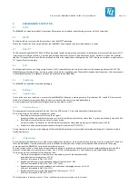
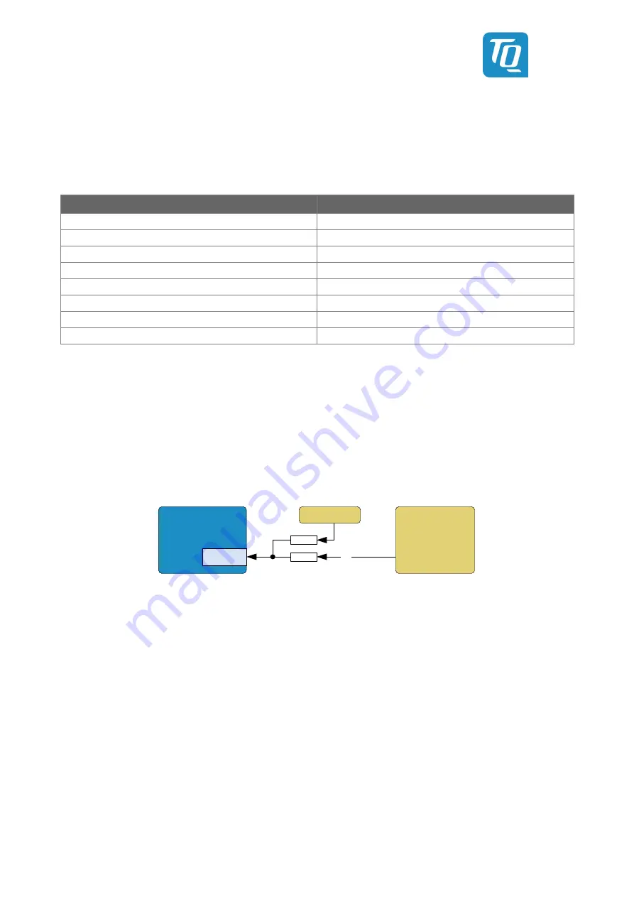
On the MBa8MPxL two push buttons are routed to a pin header and can be connected to any other signal from there.
SWITCH_B# and GPT1_CPTR2, as well as SWITCH_A# and GPT1_CLK can each be connected via 0 Ω bridges.
The signals between push button and pin header have 10 kΩ pull-ups to 3.3 V. The push buttons switch to ground.
TQMa8MPxL
Push
buttons
GPIO
Header
2x
NP
Figure 22: Block diagram pushbuttons
3.4.3
Reset button
More information can be found in chapter 3.1.7.

