User's Manual l MBa8MPxL UM 0100 l © 2022, TQ-Systems GmbH
Page 17
PCIe M.2 (continued)
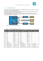
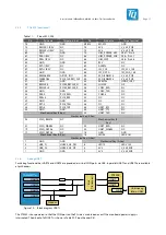
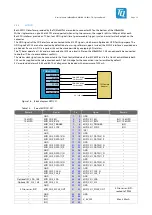
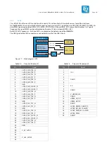
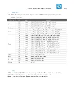
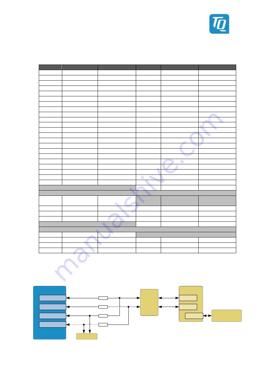
Table 11:
Pinout M.2, X48
Pin
Pin name
Target pin/net
Pin
Pin name
Target pin/net
75
GND
GND
M1/M2
M1; M2
GND
73
REFCLK-1/RSV
NC
74
3V3
V_3V3_PCIE
71
1/RSV
NC
72
3V3
V_3V3_PCIE
69
GND
GND
70
UIM_POWER_SRC
X557 – Pin 4
67
PER-1/RSV
NC
68
UIM_POWER_SNK
X46 – Pin C1
65
PER+1/RSV
NC
66
UIM_SWP
X46 – Pin C6
63
GND
GND
64
RSV
NC
61
PET-1/RSV
NC
62
ALERT#
NC
59
PET+1/RSV
NC
60
I2C_CLK
I2C_SCL_1V8
57
GND
GND
58
I2C_DATA
I2C_SDA_1V8
55
PEWAKE0#
GPIO2_IO11
56
W_DISABLE1#
V_3V3_PCIE
53
CLKREQ0#
PCIE_CLKREQ_CLK
54
W_DISABLE2#
V_3V3_PCIE
51
GND
GND
52
PERST0#
GPIO2_IO07
49
REFCLK-0
PCIE0_REFCLK_N
50
SUSCLK
G9
47
0
PCIE0_REFCLK_P
48
COEX_RXD
NC
45
GND
GND
46
COEX_TXD
NC
43
PER-0
PCIE_RXN
44
COEX3
NC
41
PER+0
PCIE_RXP
42
NC
NC
39
GND
GND
40
NC
NC
37
PET-0
PCIE_TXN
38
NC
NC
35
PET+0
PCIE_TXP
36
UART_RTS
NC
33
GND
GND
34
UART_CTS
NC
Mechanical Key (E-Key)
32
UART_TXD
NC
Mechanical Key (E-Key)
23
SDIO_RESET#
NC
Mechanical Key (E-
Key)
21
SDIO_WAKE#
NC
22
UART_RXD
NC
19
SDIO_DATA3
NC
20
UART_WAKE#
NC
17
SDIO_DATA2
NC
18
GND
GND
Mechanical Key (A-Key)
16
LED2#
LED V181
Mechanical Key (A-Key)
7
GND
GND
Mechanical Key (A-Key)
5
USB_D-
USB30_H3_DN
6
LED1#
LED V132
3
USB_D+
USB30_H3_DP
4
3V3
V_3V3_MB
1
GND
GND
2
3V3
V_3V3_MB
3.3.6
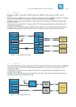
Debug UART
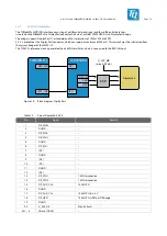
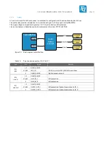
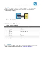
For debug functionalities UART3 and UART4 are provided as virtual COM ports via USB. In parallel UART1 and UART2 are available
at pin headers.
FT4232
TQMa8MPxL
UART4
UART1
UART
USB
USB-Debug
(Micro-USB)
UART3
UART2
UART
Header
NP
NP
Bus
Transceiver
Figure 14: Block diagram UARTs
The FT4232 is bus-powered so that the COM port on the PC side is maintained even if the mainboard power supply is
interrupted. The pinout of all UARTs is shown in Table 22, Pinout header X61.


