User's Manual l MBa8MPxL UM 0100 l © 2022, TQ-Systems GmbH
Page 24
3.3.13
ECSPI
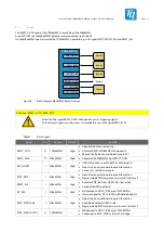
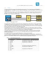
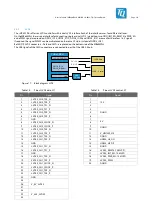
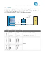
Up to three ECSPI interfaces are provided by the i.MX 8M Plus. These can be used on the MBa8MPxL for different interfaces.
ECSPI3 is used for the ADC of the IO extension; see chapter 3.3.19. ECSPI1 and ECSPI2 are connected to pin headers as well as via
0 Ω bridges to the MIPI CSI connector. There they are used as GPIO control signals.
3.3.14
SPDIF
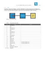
The SPDIF interface is not used as such on the MBa8MPxL, but can be provided on a pin header if required. By default these
module signals are configured as GPIO to enable the control of the user LEDs via transistors.; see chapter 3.4.4.
3.3.15
GPT
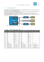
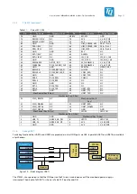
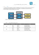
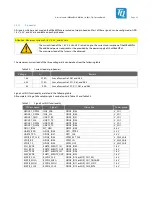
The i.MX 8M Plus provides up to three general purpose timers. Signal GPT2_CLK is used to determine the fan speed.
The module signals GPT1_CLK and GPT1_CPTR2 are configured as GPIOs by default and are used to connect the two freely
configurable buttons; see chapter 3.4.2. Alternatively, both signals can be connected to a pin header.
All three signals use I
2
C or UART pins of the i.MX 8M Plus and have 3.3 V level.
3.3.16
PWM
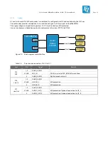
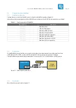
The TQMa8MPxL provides two PWM signals, of which PWM3 is used to control the fan speed; see chapter 3.1.6.
PWM2 can be provided at pin GPIO3_IO21 and thus serve the PWM control of the LVDS display.
3.3.17
CCM
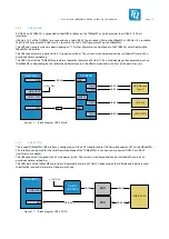
CLK1_IN and CLK2_IN of the Clock Control Module are routed on pin headers. CLK1_OUT and CLK2_OUT can be used as clock
supply for the MIPI CSI interface. The 0 Ω bridge required for this is not equipped by default. All signals operate at 1.8 V.
3.3.18
TSE chip
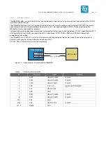
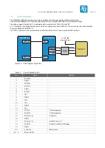
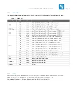
For TQMa8MPxL variants with TSE chip, the corresponding circuitry is available for the pins used.
•
The ISO 14443 interface is connected to a pin header where an antenna can be connected.
If this TSE chip interface is not used, the signals are terminated with pull-down resistors.
•
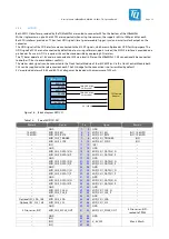
The ISO 7816 interface of the TSE chip is routed to a pin header; see chapter 3.3.20.
If this TSE chip interface is not used, the signals are terminated according to the data sheet.


