User's Manual l MBa8x UM 0100 l © 2021, TQ-Systems GmbH
Page 21
3.8
Battery
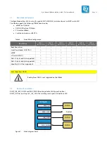
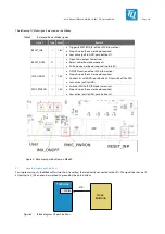
To maintain the RTC supply on the TQMa8x module when the mainboard is switched off, a CR2032 coin cell can be used on the
mainboard. A battery holder is provided for this purpose. To meet the regulatory requirements for protection of accidental
battery charging, a 1 kΩ resistor and a diode are connected in series.
Also, a two-pin header with jumper X23 is provided for additional supply to the V_LICELL level of the PMIC. Furthermore, there is
a two-pin header X55 for the connection of an external power supply.
Connector
TQMa8x
V_LICELL
Coin-Cell
Li-Coin-Cell
Super-Cap
(typ. 3 V)
PCF85063
(RTC)
VDD
V_VBAT
3,3 V
1 k
W
Jumper
PMIC
V_5V_IN
5 V
Figure 6:
Block diagram battery
3.9
LEDs
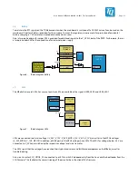
The MBa8x has several LEDs. For user outputs two LEDs are available at the signals USER_LED0 and USER_LED1.
TQMa8x
GPIO
2x
2x User-LEDs
(green)
Power-LEDs
(green)
5 V / 3,3 V / ...
RESET_OUT#
RESET-LED
(red)
Mini-PCIE-Slot
3x LEDs
(green)
Figure 7:
Block diagram LEDs
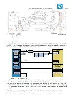
LEDs are connected to all main voltages (V_24V, V_12V, V_5V0_MOD, V_5V, V_3V3, V_1V8) as well as to the MPCIe voltages
(V_3V3_MPCIE, V_1V5_MPCIE). In addition, all USB ports at the VBUS voltages have LEDs. The LEDs for voltages below 3.3 V are
connected to V_3V3 and switched by the respective voltage level via a transistor.
The LEDs signal that the voltages have reached their typical end values and facilitate development on the MBa8x, as well as
troubleshooting.
Also via a transistor SCU_GPIO0_02 is connected to a LED to switch it independently from the Linux and the bootloader from the
SCU firmware. This facilitates the commissioning of the essential basic function of this firmware.


