User's Manual l MBa8x UM 0100 l © 2021, TQ-Systems GmbH
Page 25
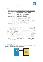
The MBa8x also provides the Enhanced Serial Audio Interface (ESAI). The ESAI0-Interface (ESAI0) is connected directly to pin
header X61. On the other hand, other signals are muxed onto ESAI1. See also c
hapter
3.14.2
SPDIF
The SPDIF interface is connected to the starter kit header X64.
3.14.3
CAN-FD
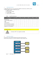
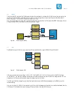
Both CAN interfaces of the MBa8x are directly connected to the CAN ports of the TQMa8x and are available at the two 3-pin
connectors X18 and X19. Both interfaces are galvanically isolated up to 1 kV. The CAN interfaces are not galvanically isolated
from each other. The CAN signals can be terminated with 120 Ω via DIP switches S10 and S11.
Galv. isolation
TQMA8x
CAN0
CAN1
3 pole
socket
3 pole
socket
CAN
Transceiver
CAN
Transceiver
Figure 11: Block diagram CAN-FD
Table 13:
CAN termination
DIP switch
Interface
ON
OFF
S10-1 & S10-2
CAN0
CAN0 terminated with 120 Ω
CAN0 not terminated
S11-1 & S11-2
CAN1
CAN1 terminated with 120 Ω
CAN1 not terminated
3.14.4
MLB
A MLB (Media Local Bus or MediaLB) is available on the CPU. This interface serves as an inter-chip bus for the connection of
MOST-PHYs (Media Oriented Systems Transport) or other MLB devices.
MLB can be implemented in two transmission modes, both of which are supported by the CPU. For applications with lower
bandwidth, the 3-pin implementation (single-ended) is available, for applications with high data rates, the 6-pin implementation
(differential). The latter allows a data rate of up to 294.912 MHz, the 3-pin version offers data rates of up to 49.152 MHz.
Only one of the interfaces can be used at a time.
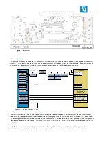
The MLB signals are connected to the 40-pin Hi-Speed connector X21. The wiring is based on Media Local Bus Specification
Version 4.2. 3.3 V and 5 V are available at the connector for the optional supply of expansion modules, each of which can supply
up to 500 mA. The power drawn must be subtracted from the available power of the starter kit headers.
620 Ω pull-down resistors are fitted to the differential signals MLB_DATA_P and MLB_SIG_P. Further pull-up and pull-down
resistors for the differential signals are not populated, as these are usually implemented by the MLB controller.
The differential MLB signals are extended and have a differential impedance of 100 Ω.
Pull-down circuits for single-ended signals are populated.
Table 14: Pinout X21
Pin Signal
Note
1
V_3V3_MB
-
2
V_5V
-
5
MLB_CLK
47 kΩ PD, 100 Ω + 27 pF PD
9
MLB_DATA
47 kΩ PD, 100 Ω
13
MLB_SIG
47 kΩ PD, 100 Ω
19
MLB_CLK_N
100 Ω nach MLB_CLKP
21
MLB_CLK_P
-
25
MLB_DATA_N
100 Ω nach MLB_DATA_P
27
MLB_DATA_P
-
31
MLB_SIG_N
100 Ω nach MLB_SIG_P
33
MLB_SIG_P
-
All pins not listed are connected to GND


