User's Manual l MBa8x UM 0100 l © 2021, TQ-Systems GmbH
Page 26
3.14.5
USB debug
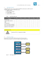
For the output of debug messages of the TQMa8x, one UART of the ARM core, a separate UART of the SCU and two further
UARTS of the M4 CPUs are used. These four UARTs are converted to USB by the FTDI FT4232. The FT4232 is a 4-port bridge.
All four COM ports are provided together on one USB port. The interface is supplied from the external USB host and is thus
independent of the MBa8x.
TQMa8x
SCU_UART
UART0
FT4232
UART
USB
USB-Debug
(USB
Micro)
mikroBUS
socket
M40_UART
M41_UART
UART
UART
UART
UART1
UART2
Pin header
Vo
lta
ge
tra
ns
la
to
r
Figure 12: Block diagram USB debug
3.14.6
Ethernet
The i.MX 8 CPU provides two independent RGMII interfaces. On the MBa8x, both interfaces are used to provide two Gigabit
Ethernet ports. The PHYs support IEEE 802.3 10BASE-Te, 100BASE-TX, and 1000BASE-T.
The I/O voltage of the RGMII signals is 1.8 V. Both PHYs are connected with their own PHY reset and interrupt signals.
Furthermore, the interrupt signal of the ENET0-PHY is connected to the module.
TQMa8x
RJ45
ENET0
RGMII0
ENET1
RGMII1
PHY #1
DP83867
PHY #2
DP83867
RJ45
ENET0_SMI
ENET1_SMI
Figure 13: Block diagram Ethernet
Table 15: Ethernet Reset and Interrupt signals
Signal
TQMa8x signal
Pin
ENET0_INT#
ESAI1_TX0
X2-A33
ENET0_RST#
ESAI1_SCKR
X2-A34
ENET1_RST#
ESAI1_FSR
X2-A35
The PHY DP83867 has boot straps to start with configurable default values. All boot straps can be customized by placement
options. Further information is available in the MBa8x schematics.
As both Ethernet interfaces have their own MDIO signals, the PHY addresses can be selected as desired. Address 0x00 is assigned
to the PHY of Ethernet 0, address 0x03 to that of Ethernet 1.
The possible data throughput is influenced by the system load and the software used. With the standard BSP, the following
transfer rates can be achieved on the MBa8x with a Gigabit link:


