User's Manual l MBa8x UM 0100 l © 2021, TQ-Systems GmbH
Page 31
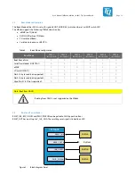
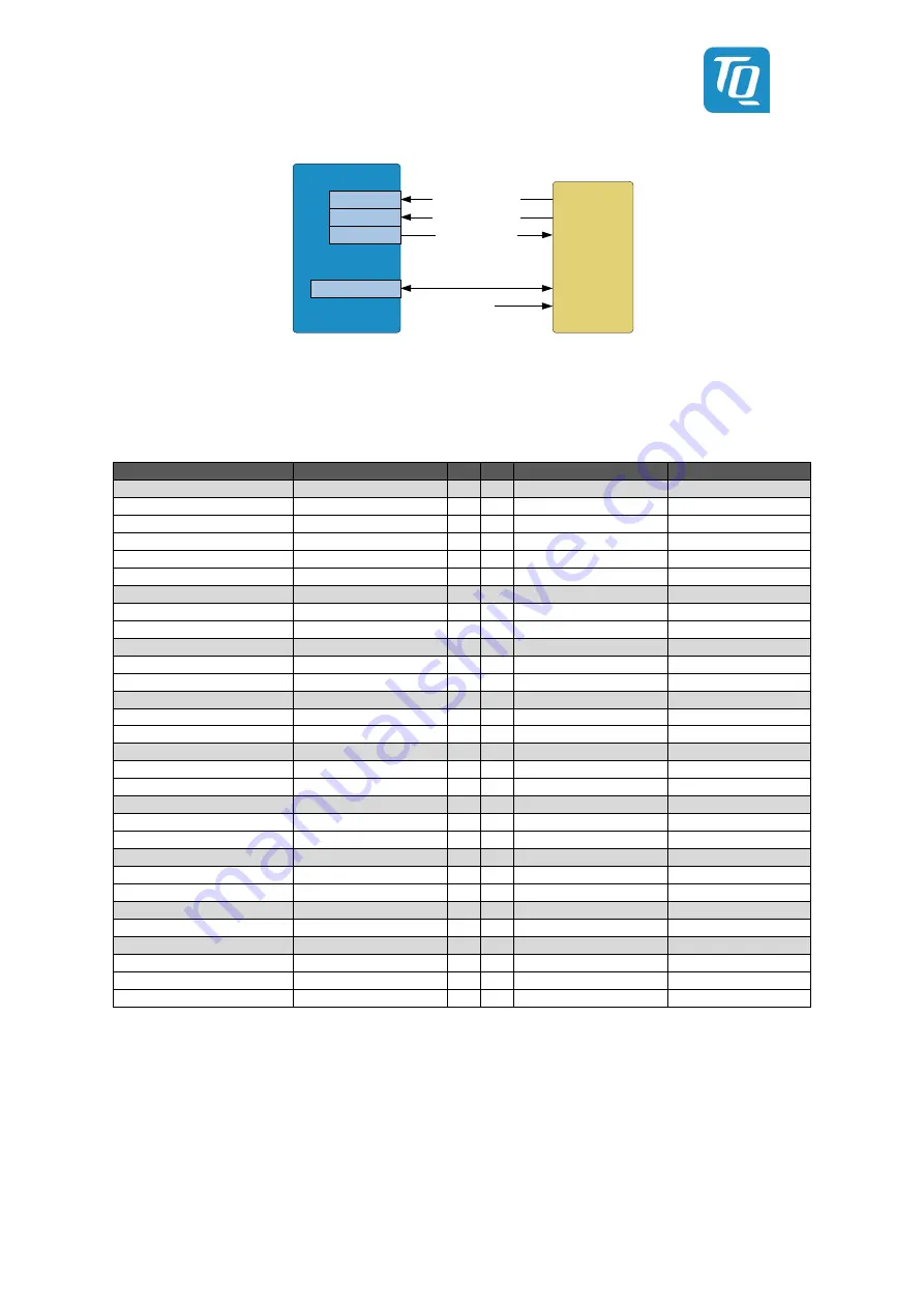
TQMa8x
MIPI_CSI0
MIPI_CSI1
TQ camera
adapter
Incl. PWR and RST
5 V / 300 mA
2x CSI_I2C
Incl. PWR and RST
GPIO
TRIGGER & Sync
Figure 16:
Block diagram MIPI-CSI / TQ Camera Interface
The interface is already used on the MB-SMARC-2 and other TQ boards. Functions have been added to the interface in
coordination with TQ EMB.
Table 20: TQ MIPI-CSI adapter
Description
Signal
Nr. Nr. Signal
Description
-
GND
1
2
GND
-
GPIO 1,8V
MIPI_CSI0_EN
3
4
CAM1_PWR#
GPIO 1,8V
GPIO 1,8V
MIPI_CSI0_RST#
5
6
MIPI_CSI1_RST#
GPIO 1,8V
GPIO 1,8V
M40_GPIO0_01
7
8
M41_GPIO0_00
GPIO 1,8V
GPIO 1,8V
M40_GPIO0_00
9
10
M41_GPIO0_01
GPIO 1,8V
Reserved
NC
11 12
NC
Reserved
-
GND
13 14
GND
-
-
MIPI_CSI0_DATA3_N
15 16
MIPI_CSI1_DATA3_N
-
-
MIPI_CSI0_DATA3_P
17 18
MIPI_CSI1_DATA3_P
-
-
GND
19 20
GND
-
-
MIPI_CSI0_DATA2_N
21 22
MIPI_CSI1_DATA2_N
-
-
MIPI_CSI0_DATA2_P
23 24
MIPI_CSI1_DATA2_P
-
-
GND
25 26
GND
-
-
MIPI_CSI0_DATA1_N
27 28
MIPI_CSI1_DATA1_N
-
-
MIPI_CSI0_DATA1_P
29 30
MIPI_CSI1_DATA1_P
-
-
GND
31 32
GND
-
-
MIPI_CSI0_DATA0_N
33 34
MIPI_CSI1_DATA0_N
-
-
MIPI_CSI0_DATA0_P
35 36
MIPI_CSI1_DATA0_P
-
-
GND
37 38
GND
-
-
MIPI_CSI0_CLK_N
39 40
MIPI_CSI1_CLK_N
-
-
MIPI_CSI0_CLK_P
41 42
MIPI_CSI1_CLK_P
-
-
GND
43 44
GND
-
-
MIPI_CSI0_SDA
45 46
MIPI_DSI1_SDA
-
-
MIPI_CSI0_SCL
47 48
MIPI_DSI1_SCL
-
-
GND
49 50
GND
-
Master Clock for CSI1
MIPI_CSI0_MCLK_OUT
51 52
MIPI_CSI1_MCLK_OUT
Master Clock for CSI1
-
GND
53 54
GND
-
Reserved for other voltage
NC
55 56
V_5V_STBY
Always on
Reserved for other voltage
NC
57 58
V_5V_STBY
Always on
Reserved for other voltage
NC
59 60
V_5V_STBY
Always on
300 mA (2x150 mA) is budgeted for the TQ camera adapter on the 5 V level. The current consumption has been determined on
the basis of the worst-case power consumption of the reference camera "Li-Apollo-adp-IMX185" from Leopard Imaging Inc of
0.63 W. If higher power is required for the connected cameras, this must be subtracted from the power provided at the starter kit
headers.
The components under the area for the adapter board must not exceed a height of 2 mm!
3.14.10
Mini PCIe
A mini PCIe card slot is realised on the MBa8x. This is connected to the PCIe0 interface. The interface is wired with all signals
provided by the standard (e.g. USB, I2C, PCIe). The clock is generated externally from a central location.

