User's Manual l MBa8x UM 0100 l © 2021, TQ-Systems GmbH
Page 34
TQMa8x
Power
switch
LVDS0
CMD
USB2.0
hub
USB2517
LVDS1
CMD
Mini-
PCIe
OTG2
USB5
USB6
USB7
EN/OC
VBUS
VBUS
Power
switch
USB-A
socket
USB-A
socket
MIPI-
DSI0
CMD
MIPI-
DSI1
CMD
Power
switch
USB1(3.0)
USB2(3.0)
USB3
USB4
EN/OC
VBUS
VBUS
VBUS
VBUS
EN/OC
USB3.0
hub
TUSB8041
USB1
USB2
n.c.
n.c.
USB4(2.0)
USB3(2.0)
PCIe M.2
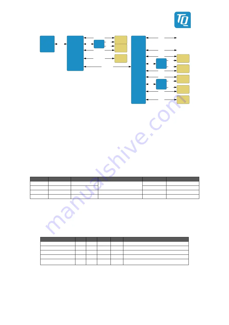
Figure 21: Block diagram USB hub structure of the MBa8x
The USB 3.0 OTG port, consisting of the OTG2 signals and the super speed signals, is used as the upstream port.
The reset pin of
the hub is connected to USB_RST# via an open-drain buffer and simultaneously brought to 3.3 V level.
USB hosts 1 and 2 are connected as USB 3.0 hosts to a dual USB type A socket (X36). USB host 3 can be tapped at the PCIe M.2
slot (X47).
On the contrary, the USB 2.0 hub USB2517 is connected to USB host 4, which serves all internal USB 2.0 hosts. Four
ports are used for the LVDS[1:0] CMD and MIPI-DSI[1:0] interfaces. A maximum of 500 mA can be drawn from each of these
connectors. The power drawn must be subtracted from the power available at the starter kit headers.
An additional 1.1 V is required for the TUSB8041. These are generated with the DC/DC converter AP7173-FN.
Power distribution
switches are used to supply the USB hosts with 5 V (VBUS). The following table shows the characteristics of the VBUS supply:
Table 21: Power-Distribution TUSB8041
USB-Hub
Interface
Power-Switch
Features
Max. current
Current-threshold
1
USB-Host
FPF2165R
Thermal-Shutdown;
Reverse Current Protection
900 mA
0.970 A …1.186 A
2
USB-Host
FPF2165R
900 mA
0.970 A …1.186 A
3
PCIe-M.2
No VBUS supply -
-
-
4
USB 2.0 Hub No VBUS supply -
-
-
The signals I2C1_SCL/SDA_3V3 are used for the I2C bus. These are already provided for the temperature sensor by a level
translator from I2C1_SCL/SDA_1V8.
The USB 3.0 OTG port of the TQMa8x provides a theoretical data rate of 5 Gbps. This is divided among the connected ports of the
USB 3.0 hub. Depending on the software and hardware used, the effective read and write rates of the ports can vary.
Table 22: Properties USB host 1 and 2
Parameter
Min. Typ. Max.
Unit
Note
Voltage
4.75
5
5.25
V
-
Current
-
-
900
mA
Current limitation to 0,970 A…1,186 A
Voltage dip at load
-
-89
-155
mV
With a load of 500 mA or 950 mA
Read rate
-
121
-
MB/s
Tested only on host 1
Write rate
-
73.2
-
MB/s
Tested only on host 1
3.14.16
USB OTG
USB OTG1 is connected as USB 2.0 OTG to a separate Micro AB USB socket and can be used for the serial downloader. The power
supply of the USB OTG port is realized via a power switch.


