User's Manual l MBLS1028A UM 0100 l © 2020, TQ-Systems GmbH
Page 11
4.2
Power supply
The MBLS1028A has to be supplied with 18 V to 28 V at X3 or X27. The typical supply voltage is 24 V.
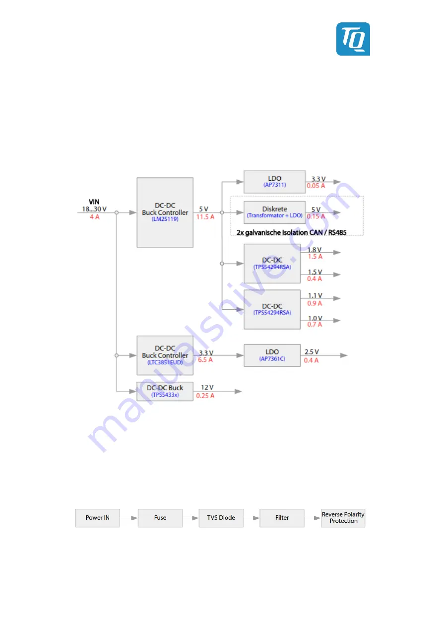
The following figure shows all voltages present on the MBLS1028A, which are structured into three main paths consisting of an
LM25119, an LTC3851 and a TPS54335. These supply the biggest loads (TQMLS1028A, USB supply, SATA supply with up to
2500 mA). The power supply structure is designed in such a way that the 5 V voltage is always activated.
Furthermore the design allows power sequencing of all voltage levels used. All voltages are powered up after the boot process of
the TQMLS1028A.
At the two headers X25 and X38 on the MBLS1028A 1.8 V, 3.3 V, 5 V and 12 V are available. Both connectors share the available
total power of the individual voltage rails.
Figure 6:
Block diagram power supply
4.2.1
Protective circuitry
The protection circuit (see Figure 7) features the following characteristics:
•
Overcurrent protection by fuse 5 A, slow blow
•
Overvoltage protection diode
•
PI filter
•
Reverse polarity protection by MOSFET
Figure 7:
Block diagram protective circuit
4.2.2
Battery
In case of power failure a lithium battery type CR2032 on the MBLS1028A supplies the RTC on the TQMLS1028A.


