background image

Assembly Instructions  |  ILM-E Servo Kits

19

Edition 10/2021 EN

Assembly


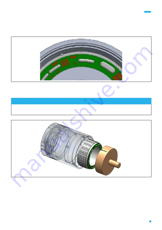
Remove the housing from the oven and align the stator in the housing as shown in 

the design guidelines.

Fig. 7:  Stator alignment

◀ 

Dowel pin


Use the press-in tool to carefully press the stator into the housing until the pole 

cap/base of the stator touches the bottom surface of the housing.

NOTE

Make sure that the alignment/positioning of the stator does not change when it is pressed in.
Be careful not to press on the PCB while pressing the stator in.

Fig. 8:  Pressing-in process

Summary of Contents for ILM-E

Page 1: ...Assembly Instructions ILM E Servo Kits Edition 10 2021 EN...

Page 2: ...ess However the information in this document is reviewed regularly and any necessary corrections are included in subsequent editions All trademarks mentioned in this manual are the property of their r...

Page 3: ...marks 7 2 Safety 8 2 1 Hazard classification 8 2 2 Target group 8 2 3 Intended use 9 2 4 Working environment and operation 9 2 5 Safety instructions for the ILM E servo kit 10 2 6 Warning labels 11 3...

Page 4: ...nternal rotor motor Evolution servo kit consists of a stator and a rotor with permanent magnets for installation in machines and devices in the com mercial environment The RoboDrive technology provide...

Page 5: ...website 1 5 Explanation of the symbols used This symbol indicates an action to be taken This symbol indicates a list 1 6 Training The manufacturer offers training courses on the general handling of th...

Page 6: ...bly or set up work was carried out without following these assembly instructions or was otherwise carried out incorrectly Unauthorised repairs Incorrect operation Incorrect use Application of force Ot...

Page 7: ...s in the vicinity of the potential risk The ILM E servo kits must not be disposed of in the residual waste bin In Germany metal and plastic components should be disposed of at the local recy cling cen...

Page 8: ...important information about the product or about a part of the manual to which particular attention should be paid 2 2 Target group The activities described in this manual must only be carried out by...

Page 9: ...or reuse for commercial or professional purposes as defined by IEC EN 61000 3 2 Intended use also includes compliance with this manual and the instructions it contains If the ILM E servo kits are to b...

Page 10: ...rotect your eyes until you have finished installing the ILM E servo kit If the ILM E servo kit is operated below the specified temperature the magnets can become detached from the rotor and fly around...

Page 11: ...arer Never touch rotating components motor shafts clutches etc Do not wear belts chains ties or clothing with wide sleeves at the workplace Wear a hairnet if you have long hair Make sure that there ar...

Page 12: ...the technical data for the ILM E servo kits in the data sheet provided in the ILM E servo kits download area 3 2 Connection diagram star serial configuration Connections A B and C can be found on the...

Page 13: ...a Nominal current In A Terminal resistance RTT at 20 C m Terminal inductance LTT H Table 2 Measuring points on the ILM E servo kit star serial configuration 3 3 Installation dimensions The installatio...

Page 14: ...lder pads on the connection board 4 SOLDER PADS ON THE CONNECTION BOARD Fig 4 shows the solder pads on the connection board by way of example Detailed drawings for your specific ILM E servo kit can be...

Page 15: ...safe distance of at least 2 m Instruct persons in the vicinity of the potential risk Attach warning instructions stating POWERFUL MAGNETIC FIELDS to the packaging at the installation area and at the s...

Page 16: ...time even after the power supply to the entire system is switched off Never detach electrical connections on the ILM E servo kit or the inverter while they are live Use a permitted meter to check that...

Page 17: ...nts Antistatic coat ESD grounding wrist strap Safety goggles Protective gloves Assembly sleeve Drawing available as a download Dimensions according to the outer diameter of the stator as shown in the...

Page 18: ...ection for your hands throughout the entire process Clean and degrease the housing and stator with isopropyl alcohol Apply a small amount of adhesive in the groove identified for the dowel pin in the...

Page 19: ...s Fig 7 Stator alignment Dowel pin Use the press in tool to carefully press the stator into the housing until the pole cap base of the stator touches the bottom surface of the housing NOTE Make sure t...

Page 20: ...ry and skin irritation by adhesives The adhesives used for bonding can cause severe eye injuries and skin irritations Wear safety goggles to protect your eyes and wear safety gloves until you have fin...

Page 21: ...1 on the rotor Align the rotor so that the indexing hole item 2 in Fig 12 points towards the shaft see Fig 12 Push the rotor item 1 in Fig 12 onto the shaft item 3 in Fig 12 and gently push it as far...

Page 22: ...guide to prevent the rotor moving suddenly towards the stator due to magnetic attraction Wear safety goggles to protect your eyes and wear safety gloves until you have fin ished installing the ILM E...

Page 23: ...dertake in response to a reasoned request to supply it in electronic form to the market surveillance authorities within a reasonable period T Th he e f fo ol ll lo ow wi in ng g p pe er rs so on n i i...

Page 24: ...2 Gut Delling 82229 Seefeld Germany Phone 49 8153 9308 0 Fax 49 8153 4223 info tq group com www tq robodrive com TQ Systems GmbH 2021 All data is for information only Subject to change without prior n...

Reviews: