


Assembly Instructions | ILM Servo Kits
17
Edition 03/2021 EN
Solder pads on the connection board
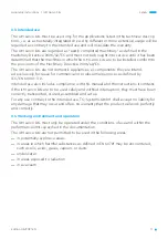
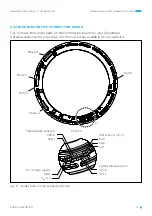
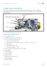
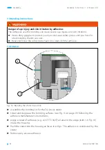
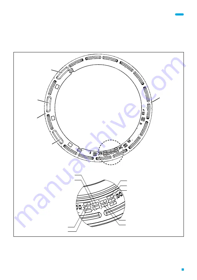
5 SOLDER PADS ON THE CONNECTION BOARD
Fig. 9 shows the solder pads on the connection board by way of example.
Detailed drawings for your type of ILM servo kit are available on our website.
Fig. 9: Solder pads on the connection board
Notch
Notch
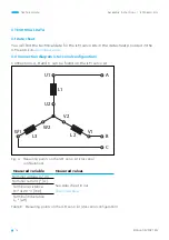
Phase A
Phase C
Phase B
A
Detail A
Temperature sensor 2
SP2-2
SP2-1
5 V voltage supply
GND
V
CC
5 V
Hall sensors 1/2/3
SA3
SA2
SA1
Temperature sensor 1
SP1-2
SP1-1


