User's Manual l MBa8Xx UM 0100 l © 2020, TQ-Systems GmbH
Page 43
3.10
Power supply
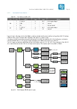
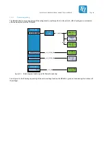
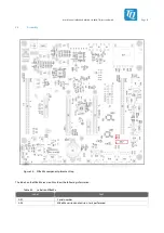
The MBa8Xx can be supplied at two connectors X26 and X27, which can be used alternatively.
The MBa8Xx has to be supplied with 24 V DC (typ.) via one of these connectors.
3.10.1
Input protection
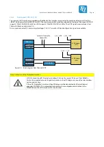
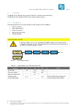
The following protective circuits are provided for the input voltage V_24V of the MBa8Xx:
•
Fuse 4 A, slow blow
•
Overvoltage protection
•
PI Filter (CLC element)
•
Reverse polarity protection
•
Voltage stabilization
Attention: Voltages at headers
The internal voltages (1.8 V, 12 V, etc.) provided at the MBa8Xx headers are not separately fused.
Technically an overload of the fuse is therefore possible. The resulting total current consumption of
the MBa8Xx should be kept below 4 A in total.
2-pin terminal
(X27)
DC jack
(X26)
Overcurrent
Filter
Overvoltage
Polarity
V_24V
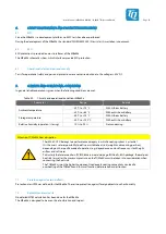
Figure 21: Block diagram Power-In
Table 48:
Supply voltage V_24V_IN at Power-In (X26, X27)
Parameter
Min.
Typ.
Max.
Remark
Input voltage
16 V
24 V
26.7 V
–
Power consumption
–
TBD
(34)
95 W
(35)
–
Rated current of the fuse
–
4 A
–
–
Voltage limitation
in case of overvoltage
26.7 V
–
29.5 V
Note: The MBa8Xx may be damaged
in case of permanent overvoltage!
34:
Typical scenario is not defined.
35:
Theoretical full load. All supply voltages are loaded with maximum current, e.g. by connecting additional load to the pin headers, and all system components
have maximum power consumption.

