User's Manual l MBa8Xx UM 0100 l © 2020, TQ-Systems GmbH
Page 6
3.
ELECTRONICS
The following chapters describe the interfaces of the MBa8Xx as of revision 02xx in connection with a TQMa8Xx or TQMa8Xx4
with maximum configuration. If not described differently, all descriptions apply to both TQMa8Xx and TQMa8Xx4.
For better readability, the TQMa8Xx is therefore named for both, the TQMa8Xx and the TQMa8Xx4.
In any case the TQMa8Xx User's Manual must be complied with.
3.1
TQMa8Xx
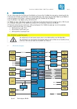
The TQMa8Xx is the central system on the MBa8Xx. It provides DDR3L SDRAM (TQMa8Xx), or LPDDR4 SDRAM (TQMa8Xx4),
eMMC, NOR flash, RTC, an EEPROM, power supply and power management functionality.
All TQMa8Xx internal voltages are derived from the 3.3 V supply voltage. All functionally relevant pins of the CPU are routed to
the TQMa8Xx connectors. This enables the user to use the TQMa8Xx with all the freedom that comes with a customer-specific
design-in solution. Further information can be found in the TQMa8Xx User’s Manual.
On the MBa8Xx the standard interfaces like USB, Ethernet, etc., provided by the TQMa8Xx are routed to industry standard
connectors. All other signals and buses provided by the TQMa8Xx are routed to 100 mil headers.
The boot behaviour of the TQMa8Xx can be configured.
The Boot Mode configuration is set by a DIP switch on the MBa8Xx, see chapter 3.2.
Furthermore the MBa8Xx provides all power supplies and configurations required for the operation of the TQMa8Xx.
i.MX 8DUALX
PLUS
i.MX 8DUALXPLUS
i.MX 8QUADXPLUS
DDR3L or
LPDDR4
Connector 120 pins
eMMC 5.1
EEPROM
Temperature
sensor
PMIC
PF8100/PF8200
Connector 120 pins
2 × QSPI NOR
flash (optional)
3.
3
V
RTC (optional)
Connector 40 pins
Figure 2:
Block diagram TQMa8Xx


