User's Manual l MBa8Xx UM 0100 l © 2020, TQ-Systems GmbH
Page 19
USB hub (continued)
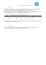
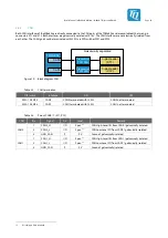
Table 17:
USB hub Power Management
Config pin on USB hub
Default value MBa8Xx
Description
FULLPWRMGMT#
0
Power Management and Overcurrent inputs active
PWRCTRL_POL
1
PWRCTLx signals are high-active
GANGED
0
Power Management is done individually for each downstream port
AUTOEN#
1
Automatic Charge Mode is deactivated
SMBUS#
1
I²C mode
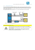
The VBUS supply and overcurrent monitoring of the respective USB hosts (except Mini PCIe) is done by power distribution
switches. The Mini PCIe interface does not require VBUS voltage.
The USB hub can be configured via the I2C1 bus (optional, see Table 19).
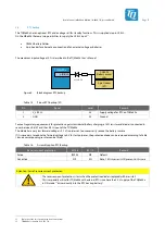
By default the Global Power Reset of the USB hub is connected to the RESET_OUT# signal of the TQMa8Xx. If necessary, the reset
source can be changed via resistor assembly option, so that the reset is triggered by a signal from the GPIO port expander (see
also chapter 3.4).
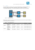
Table 18:
Assembly option Reset USB hub
Reset source / signal
R383
R384
R385
Remark
TQMa8Xx (RESET_OUT#)
NP
NP
0 Ω
Default
GPIO Port Expander (USB_RESET#)
10 kΩ
0 Ω
NP
–
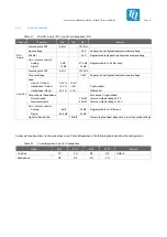
By default the I2C1 bus is not connected to the USB hub. This can be done by assembling two resistors, as shown in the table
below.
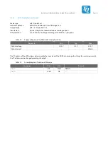
Table 19:
Assembly option I2C1 bus am USB hub
I2C1 bus
R201
R202
Remark
Not connected
NP
NP
Default
Connected
0 Ω
0 Ω
–


