background image


Printed in the Federal Republic of Germany 

 TR-Electronic GmbH 2013, All Rights Reserved 

02/21/2018 

TR - ECE - BA - GB - 0101 - 05 

Page 11 of 29 

2.4 Intended use 

 
The  equipment  is  used  for  the  detection  of  angular  movements  as  well  as  the 
processing  of  the  measurement  data  for  a  downstream  control  through  industrial 
process- and control procedures. 
 
The equipment is a fixed-installation device for use in the Ex-Zone 2 (potentially gas-
explosive areas, Il 3 G, device protection level Gc) or 22 (areas with combustible dust 
II 3 D, device protection level Dc). 
 
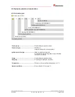
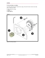
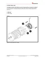
The  assembly  takes  place  through  the  established  attachment  possibilities.  The 
electrical data provided on the nameplate, as well as the device category, temperature 
class etc. for the place of use are to be observed. The operating temperature range of 
the equipment is -20°C to +60°C. 


Intended use also includes: 

  observation  of  all  instructions  contained  in  this 

-User  manual  and  in  the 

interface-specific user manual, 

  observation of the nameplate and possible prohibition- or instruction labels on the 

equipment, 

  observation of the supplementary documentation e.g. the accompanying product 

sheet, connector assignments etc., 

  observation of the machine- or system manufacturer's operating manual, 

  operating of the equipment within the limits indicated in the technical data 

(

-User manual/interface-specific user manual). 


2.5 Non-intended use 


Risk of death, bodily injury or damage resulting from non-intended use of 
the equipment!


Since the equipment is 

not a safety component

 according to the EC-

machine directive, a plausibility test of the measuring-system-values has to 
be performed through the downstream control. 


It is compulsory for the operator to incorporate the equipment into their own 
safety system. 


The following uses are especially prohibited: 

in environments with an explosive atmosphere of the Zones 
0, 1, 20 and 21 

for medical aims  

commissioning of the equipment if the nameplate is no longer readable 
or is completely missing. 


Summary of Contents for AES58

Page 1: ...on protection characteristics _Assembly TR Explosionsschutzgeh use A V70 A W70 A 88 TR Explosion Protection Enclosure with integrated measuring system Explosion Protection Enclosure Type _A 58 II 3 G...

Page 2: ...anslation as well as electronic and photographic archiving or modification requires the author s written authorization Infringements will lead to liability for damage compensation The right to amendme...

Page 3: ...is product 10 2 4 Intended use 11 2 5 Non intended use 11 2 6 Warranty and liability 12 2 7 Organizational measures 12 2 8 Personnel selection and qualification basic obligations 13 2 8 1 Electrical i...

Page 4: ...8 5 Assembly 21 5 1 Solid shaft 21 5 1 1 Flange assembly 21 5 1 2 Clamp flange assembly 22 5 1 3 Fixing clamps assembly 23 5 1 4 Servo clamps assembly 24 5 2 Blind hollow shaft 25 6 Equipotential bond...

Page 5: ...1 2018 TR ECE BA GB 0101 05 Page 5 of 29 Amendment index Amendment Date Index First edition 05 08 13 02 New production series AMV58 Standards Version numbers modified 08 05 14 03 EU directives 2014 30...

Page 6: ...Since the documentation has a modular structure this User manual represents a supplement to the other documentation such as for example product data sheets dimensional drawings and leaflets etc The Us...

Page 7: ...ed and finished under compliance with the applicable European or International standards and directives EU Directives 2004 108 EC valid until 04 19 2016 2014 30 EU valid from 04 20 2016 Electromagneti...

Page 8: ...anges in angle for fixed installations The changes in angle are transmitted to the evaluation electronics via shaft The explosion protection enclosure has the ignition protection type n non sparking o...

Page 9: ...rious injury can occur if the required precautions are not met means that minor injuries can occur if the required precautions are not met means that damage to property can occur if the required preca...

Page 10: ...t hereafter referred to as equipment is manufactured using the latest technology and according to recognized safety regulations Nevertheless non intended use can cause danger to life and limb of the u...

Page 11: ...contained in this User manual and in the interface specific user manual observation of the nameplate and possible prohibition or instruction labels on the equipment observation of the supplementary do...

Page 12: ...incidents caused by external forces or acts of God 2 7 Organizational measures The User manual must always be kept within reach in the equipment s operating location In addition to the User manual th...

Page 13: ...al workers and planners the IEC 60079 14 or DIN EN 60079 14 standards are to be additionally consulted suppliers e g Beuth Verlag GmbH VDE Verlag GmbH 2 8 2 Inspection maintenance and repair The inspe...

Page 14: ...hazardous environmental influences which limit the intended use of the equipment This could be protection against aggressive fluids or weather protection for example During installation the IEC 60079...

Page 15: ...ed with before recommissioning The equipment does not require any maintenance by the operator Nevertheless inspections must be performed at regular intervals Visual inspection of the enclosure for dam...

Page 16: ...9 TR ECE BA GB 0101 05 02 21 2018 3 Transport Storage Transport instructions Do not drop the device or allow hard impacts Only use the original packaging Inappropriate packaging material may cause dam...

Page 17: ...gular acceleration 104 rad s2 Moment of inertia AE 58 typically 2 5 10 6 kg m2 AM 58 typically 1 3 10 6 kg m2 Start up torque at 20 C typically 2 Ncm Mass 0 3 0 5 kg 4 3 Environmental conditions Vibra...

Page 18: ...rved Printed in the Federal Republic of Germany Page 18 of 29 TR ECE BA GB 0101 05 02 21 2018 4 4 Enclosure materials Aluminum design Enclosure material Al Mg Si 0 5 F22 Flange material EN AW AlCu6BiP...

Page 19: ...n protection type IEC CENELEC Labeling IEC CENELEC Device category ATEX Device group ATEX Ex labeling ATEX Device group II potentially gas explosive areas Device category 3G Zone 2 adequate safety wit...

Page 20: ...group II potentially dust explosive areas Device category 3D Zone 22 adequate safety with normal operation Ignition protection type tc Protection by enclosure with adherence to the type of protection...

Page 21: ...by means of the coupling This avoids excessive loads Danger of explosion through the use of couplings which are not suitable for use in potentially explosive areas Only couplings may be used which ar...

Page 22: ...e 22 of 29 TR ECE BA GB 0101 05 02 21 2018 5 1 2 Clamp flange assembly The centring collar with proper fit assures the centring of the shaft Attachment to the machine takes place via a clamp flange 1...

Page 23: ...Page 23 of 29 5 1 3 Fixing clamps assembly The centring collar with proper fit assures the centring of the shaft Attachment to the machine takes place via 2 fixing clamps which are mounted with 4 bol...

Page 24: ...29 TR ECE BA GB 0101 05 02 21 2018 5 1 4 Servo clamps assembly The centring collar with proper fit assures the centring of the shaft Atachment to the machine takes place via three servo clamps 1 ATEX...

Page 25: ...nd hollow shaft is connected to the drive shaft via a clamp ring The rotating of the equipment caused by the resulting torque is prevented through a torque holder spring plate The occurring axial or r...

Page 26: ...6 of 29 TR ECE BA GB 0101 05 02 21 2018 6 Equipotential bonding conductor Connection An equipotential is required for systems in potentially explosive areas This is to be done with a minimum wire diam...

Page 27: ...ic of Germany TR Electronic GmbH 2013 All Rights Reserved 02 21 2018 TR ECE BA GB 0101 05 Page 27 of 29 7 Disposal Electronic waste is hazardous waste The applicable country specific regulations are t...

Page 28: ...Annex TR Electronic GmbH 2013 All Rights Reserved Printed in the Federal Republic of Germany Page 28 of 29 TR ECE BA GB 0101 05 02 21 2018 8 Annex 8 1 EU declaration of conformity...

Page 29: ...T 15 2 TR V TI GB 0060 490 00310 Info USB PC Adapter V4 TR E TI DGB 0074 49 110 xxx Info Fixing clamps Servo clamps TR V TI GB 0400 490 01001 Software and Support DVD GSD EDS type and XML files Docume...

Reviews: