background image


TR 

ECE

 -

 BA

 -

 G

014

01


 0

6/

12

/2019


Safety Manual 


_

Basic safety instructions 

_

Intended use 

_

General functional description 

_

General characteristics 

_

Assembly 

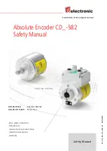
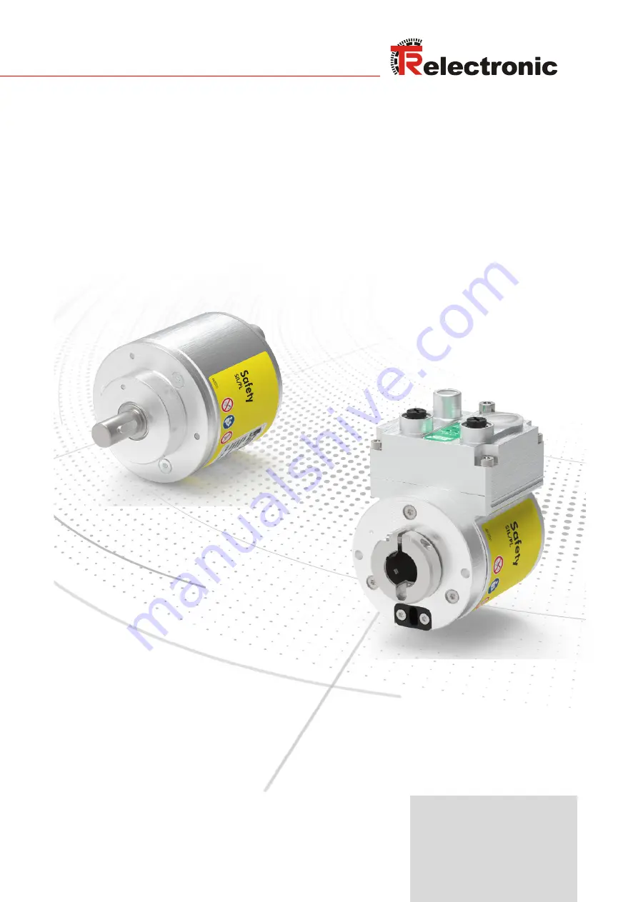
Pictures show similar items 

DIN EN 61508: 

SIL CL2 / SIL CL3 

DIN EN ISO 13849: 

PL d / PL e 

Translation of the original manual


Absolute Encoder CD_-582 
Safety Manual


Summary of Contents for CD_-582 Series

Page 1: ...ety instructions _Intended use _General functional description _General characteristics _Assembly Pictures show similar items DIN EN 61508 SIL CL2 SIL CL3 DIN EN ISO 13849 PL d PL e Translation of the...

Page 2: ...ication require the written content of the manufacturer Violations shall be subject to claims for damages Subject to modifications The right to make any changes in the interest of technical progress i...

Page 3: ...e 12 2 6 Non intended use 12 2 7 Usage in explosive atmospheres 13 2 8 Combination measuring system and draw wire box CDW582 13 2 9 Safety functions of the fail safe processing unit 15 2 10 Warranty a...

Page 4: ...Contents TR Electronic GmbH 2019 All Rights Reserved Printed in the Federal Republic of Germany Page 4 of 29 TR ECE BA GB 0142 01 06 12 2019 9 Accessories 28 10 Document Download 29...

Page 5: ...Federal Republic of Germany TR Electronic GmbH 2019 All Rights Reserved 06 12 2019 TR ECE BA GB 0142 01 Page 5 of 29 Revision index Modification Date Index First release 05 28 19 00 Draw wire box add...

Page 6: ...ngs brochures interface specific user manuals etc 1 1 Applicability This Manual applies exclusively to measuring system series according to the following keys for article numbers and types Article num...

Page 7: ...apter 10 Pin assignments on Page 29 4 Supply voltage range max power consumption see Chapter 10 Product data sheets on Page 29 Class 2 power supply unit with UL CSA approval see Chapter 2 4 on Page 11...

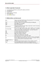
Page 8: ...ical possibility that an error occurs Functional safety Part of the overall system safety which depends on the correct functioning of safety instrumented systems for risk reduction Functional safety i...

Page 9: ...scanning units or variant 2 two magnetic scanning units are arranged on a drive shaft that is designed either as a hollow shaft a blind hole shaft or as a solid shaft The measuring system has primaril...

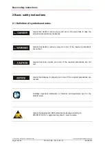
Page 10: ...to take the respective precautionary measures means that death or serious injury can occur if the required precautions are not met means that minor injuries can occur if the required precautions are...

Page 11: ...e risk remaining after application of all protective measures Risk itself is defined as the combination of the likelihood of a hazard and the severity of the potential damage During the entire safety...

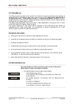
Page 12: ...f the measuring system lies with the system manufacturer Intended use also includes following all instructions provided in the other applicable documents observing the nameplate and any prohibition or...

Page 13: ...meets explosion protection requirements the properties of the measuring system will no longer be as they were originally Following the specifications in the User Manual please check whether the prope...

Page 14: ...ible level of safety that can be achieved For mechanical reasons draw wires only have a limited number of cycles which in turn is strongly dependent on the type used In practice this means that the dr...

Page 15: ...itted to the responsible organization along with the order confirmation or on conclusion of the contract at the latest Warranty and liability claims are excluded in the event of personal injury or dam...

Page 16: ...ring system are always legible Do not modify the measuring system in any mechanical or electrical way the only modifications allowed are those expressly described in the other applicable documents Rep...

Page 17: ...ures must be taken at the place of installation to prevent the temperature falling below the dew point condensation Potential hazards resulting from interactions with other systems and equipment which...

Page 18: ...9 The measuring system contains components and assemblies susceptible to electrical discharge which can be destroyed if incorrectly handled Do not touch the connection contacts of the measuring system...

Page 19: ...rity Level or Performance Level depends on the device and is noted on the nameplate DIN EN 61508 Part 1 7 Safety Integrity Level SIL CL2 or CL3 EN ISO 13849 1 Performance Level PLd Cat 3 or PLe Cat 4...

Page 20: ...t up torque will be increased This fact must be taken into account during assembly and when providing the shaft drive 5 1 Solid shaft 5 1 1 Requirements The following instructions are not exhaustive a...

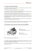
Page 21: ...c GmbH 2019 All Rights Reserved 06 12 2019 TR ECE BA GB 0142 01 Page 21 of 29 Figure 1 Installing the flange illustration showing the principle Components 1 Measuring system 2 Parallel key 3 Centering...

Page 22: ...asuring system There may be no axial load on the clamping mechanism of the measuring system The screw of the clamping ring must be tightened with 3 Nm using a torque wrench The screw of the clamping r...

Page 23: ...g7 fit provided by customer 7 Clamping ring with screw tightening torque 3 Nm secured against loosening 8 Measuring system shaft with H7 fit according to article number in referenced drawing Dimension...

Page 24: ...ce with the specifications and requirements in Chapter Assembly on Page 20 The new measuring system must be connected in accordance with the specifications in the interface specific User Manual Since...

Page 25: ...ets Page 29 Interface specific User Manual Checklist part 2 of 2 Meeting the assembly requirements defined in the Safety Manual Safe mechanical attachment of the measuring system and safe form locking...

Page 26: ...st be checked before restarting Interface specific User Manual Checklist part 2 of 2 Device replacement Ensure that the new device corresponds to the replaced device All affected safety functions must...

Page 27: ...exceeded within a service life of 20 years the metering system must be taken out of service and sent to the manufacturer After 20 years of use the measuring system must be subjected to a proof test Fo...

Page 28: ...sories Designation Part number Protective cap yellow M12x1 female thread with O ring IP65 Suitable for supply voltage connector 62 000 1664 Protective cap black M12x1 male thread without O ring IP50 S...

Page 29: ...0142 Interface specific User Manuals Designation Link PROFINET PROFIsafe www tr electronic de f TR ECE BA GB 0139 Pin assignments Link https www tr electronic com service downloads pin assignments htm...

Reviews: