background image


Printed in the Federal Republic of Germany 

 TR-Electronic GmbH 2008, All Rights Reserved 

06/27/2017 

TR - ECE - BA - DGB - 0073 - 07 

Page 15 of 155 

4 Installation / Inbetriebnahmevorbereitung 

 
EtherNet/IP

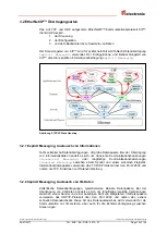
™-Netzwerke  nutzen  in  der  Regel  eine  aktive  Sterntopologie,  in  der  die 

Geräte  über  eine  Punkt-zu-Punkt-Verbindung  an  einen  Switch  angeschlossen  sind. 
Ein Vorteil einer Sterntopologie liegt darin, dass sie Geräte mit einer Übertragungsrate 
von 10 Mbit/s, wie auch von 100 Mbit/s unterstützt. Ebenso kann man Geräte beider 
Übertragungsraten  miteinander  kombinieren,  da  die  meisten  Ethernet-Switches  die 
Übertragungsgeschwindigkeit automatisch aushandeln. 
 
Für die Übertragung nach dem 100Base-TX Fast Ethernet Standard sind Patch-Kabel 
der  Kategorie  STP  CAT5e  zu  benutzen  (2  x  2  paarweise  verdrillte  und  geschirmte 
Kupferdraht-Leitungen).  Die  Kabel  sind  ausgelegt  für  Bitraten  von  bis  zu  100  Mbit/s. 
Die  Übertragungsgeschwindigkeit  wird  vom  Mess-System  automatisch  erkannt  und 
muss  nicht  durch  Schalter  eingestellt  werden.  Der  Schirm  ist  nur  auf  einer  Seite  zu 
erden. 
 
Für  die  Übertragung  ist  Voll-Duplex  Betrieb  zu  benutzen.  Für  den  Aufbau  des 
EtherNet/IP

™-Netzwerks wird der Einsatz von Switches mit folgenden Eigenschaften 

empfohlen: 
●  für die E/A-Kommunikation: 

–  Voll-Duplex tauglich, auf allen Ports 
–  IGMP-Snooping  -  beschränkt  Multicast-Datenverkehr  auf  die  Ports  mit 

zugehöriger IP Multicast Gruppe. 

–  IGMP Query – Router (oder Switch) mit aktiver IGMP-Funktion verschicken 

periodisch  Anfragen  (Query),  um  zu  erfahren,  welche  IP-Multicast-
Gruppen-Mitglieder im LAN angeschlossen sind. 

–  Port Mirroring – erlaubt das Spiegeln von Datenverkehr von einem Port auf 

einen anderen, wichtig zur Fehlersuche. 

●  sonstige Switch-Funktionen: 

–  z.B. Redundante Stromversorgung 
–  Ferndiagnosemöglichkeiten 

 
Die  EtherNet/IP

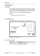
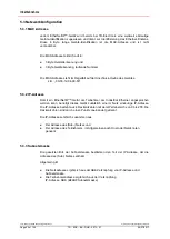
™  Node-ID  kann  entweder  über  zwei  Drehschalter,  Flash-

Konfiguration oder DHCP eingestellt werden. 
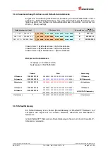
Die Kabellänge zwischen zwei Teilnehmern darf max. 100 m betragen. 


Um einen sicheren und störungsfreien Betrieb zu gewährleisten, sind die 

ISO/IEC 11801, EN 50173 (europäische Standard) 

ISO/IEC 8802-3 

IAONA Richtlinie „Industrial Ethernet Planning and Installation“ 
http://www.iaona-eu.com 

Rockwell Publikation „EtherNet/IP™ Performance and Application Guide“ 
Nr.: ENET-AP001A-EN-P 

Rockwell  Publikation 

„Ethernet/IP™-Medien  Handbuch  zur  Planung  und 

Installation

“, Nr.: ENET-IN001A-DE-P 

Rockwell Publikation 

„Richtlinien zur störungsfreien Verdrahtung und Erdung 

von industriellen Automatisierungssystemen

“, Nr.: 1770-4.1DE 

und sonstige einschlägige Normen und Richtlinien zu beachten! 


Insbesondere sind die EMV-Richtlinie sowie die Schirmungs- und Erdungsrichtlinien 
in den jeweils gültigen Fassungen zu beachten!


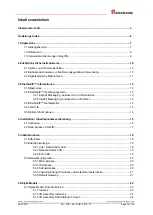
Summary of Contents for CEK-65

Page 1: ...5 D GB _Zus tzliche Sicherheitshinweise _Installation _Inbetriebnahme _Parametrierung _Fehlerursachen und Abhilfen _Additional safety instructions _Installation _Commissioning _Parameterization _Cause...

Page 2: ...und fotografische Archivierung und Ver nderung bedarf der schriftlichen Genehmigung durch den Hersteller Zuwiderhandlungen verpflichten zu Schadenersatz nderungsvorbehalt Jegliche nderungen die dem te...

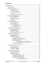
Page 3: ...2 1 Explicit Messaging Austausch von Informationen 13 3 2 2 Implicit Messaging Austausch von I O Daten 13 3 3 EtherNet IP Ger teprofile 14 3 4 Vendor ID 14 3 5 Weitere Informationen 14 4 Installation...

Page 4: ...e Codes 40 7 6 Object 0x23 Position Sensor 41 7 6 1 Gemeinsame Services 41 7 6 2 Class Attributes 41 7 6 3 Instance 1 Attributes 42 7 6 3 1 Attribute 0x02 Attribute List 43 7 6 3 2 Attribute 0x0B Posi...

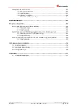
Page 5: ...Inbetriebnahme Hilfen 64 9 1 IP Parameter ber DHCP Server beziehen 64 9 1 1 Voraussetzungen 64 9 1 2 Vorgehensweise 64 9 2 IP Parameter ber TRWinProg programmieren und im FLASH speichern 67 9 2 1 Anb...

Page 6: ...ausgabe 27 11 08 00 Neu Kapitel 8 Verbindungstypen Seite 63 17 12 08 01 Zus tzliche Hinweise Parameter bernahme und Speicherung 05 10 10 02 Warnhinweise aktualisiert EDS Version neutral gehalten 13 03...

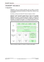
Page 7: ...nutzerhandbuch eine Erg nzung zu anderen Dokumentationen wie z B Produktdatenbl tter Ma zeichnungen Prospekte und der Montageanleitung etc dar Das Benutzerhandbuch kann kundenspezifisch im Lieferumfan...

Page 8: ...ollision Detection CSMA CD Access Method and Physical Layer Specifications 4 RFC768 Definiert das User Datagram Protocol UDP 5 RFC791 Definiert das Internet Protocol IP 6 RFC792 Definiert das Internet...

Page 9: ...namische Zuweisung einer IP Adresse DNS Domain Name System Namensaufl sung in eine IP Adresse EDS Electronic Data Sheet elektronisches Datenblatt EMV Elektro Magnetische Vertr glichkeit Gateway Verbin...

Page 10: ...onen bzw Merkmale und Anwendungstipps des verwendeten Produkts 2 2 Erg nzende Hinweise zur bestimmungsgem en Verwendung Das Mess System ist ausgelegt f r den Betrieb in 100Base TX Fast Ethernet Netzwe...

Page 11: ...stems griffbereit aufbewahrt werden Das mit T tigkeiten am Mess System beauftragte Personal muss vor Arbeits beginn die Montageanleitung insbesondere das Kapitel Grundlegende Sicherheitshinweise und d...

Page 12: ...fikation und Pflege des EtherNet IP Standards obliegen der ODVA EtherNet IP geh rt wie ControlNet und DeviceNet zur Familie der CIP basierten Netzwerke CIP Common Industrial Protocol bildet die gemein...

Page 13: ...atenpakete Bei der bertragung von Informationsdaten handelt es sich um transiente Kommunikationsbeziehungen Unconnected Messaging oder langfristige Kommunikationsbeziehungen Connected Messaging zwisch...

Page 14: ...System wurde die Ger te Typ Nummer 22hex f r Encoder festgelegt 3 4 Vendor ID Die Vendor IDs Herstellerkennungen werden von der ODVA vergeben und verwaltet Die Vendor ID von TR Electronic f r EtherNe...

Page 15: ...ommunikation Voll Duplex tauglich auf allen Ports IGMP Snooping beschr nkt Multicast Datenverkehr auf die Ports mit zugeh riger IP Multicast Gruppe IGMP Query Router oder Switch mit aktiver IGMP Funkt...

Page 16: ...ded 1 11 27 V DC Versorgung 1 3 2 4 2 TRWinProg nur f r Servicezwecke 3 GND 0V Versorgung 4 TRWinProg nur f r Servicezwecke F r die Versorgung sind paarweise verdrillte und geschirmte Kabel zu verwend...

Page 17: ...t IP Node Adresse Netz ID Host ID Tabelle 1 Aufbau der Ipv4 Adresse Die Node Adresse wird ber zwei HEX Drehschalter eingestellt welche nur im Einschaltmoment gelesen werden Nachtr gliche Einstellungen...

Page 18: ...S Datei wird durch das EtherNet IP Netzwerkkonfigurationswerkzeug eingebunden um das Mess System ordnungsgem konfigurieren bzw in Betrieb nehmen zu k nnen Die EDS Datei hat den Dateinamen 04710022_TR_...

Page 19: ...en ON Verbindung hergestellt Ger t hat mindestens eine Verbindung hergestellt z B zum Message Router 1 Hz gr n rot Selbsttest Ger t f hrt im Einschaltmoment einen Selbsttest durch 5 2 3 Error LED LED...

Page 20: ...Ger tes z B 00 03 12 04 00 60 5 3 2 IP Adresse Damit ein EtherNet IP Ger t als Teilnehmer am Industrial Ethernet angesprochen werden kann ben tigt dieses Ger t zus tzlich eine im Netz eindeutige IP Ad...

Page 21: ...Hostadresse Class B Netz 2 Byte Netzadresse 2 Byte Hostadresse Class C Netz 3 Byte Netzadresse 1 Byte Hostadresse Beispiel zur Subnetzmaske IP Adresse 130 094 122 195 Netzmaske 255 255 255 224 Dezimal...

Page 22: ...enen Variablen Attributes die die Eigenschaften dieser Instanz beschreiben Unterschiedliche Instanzen einer Klasse haben die gleichen Dienste Services das gleiche Verhalten Behavior und die gleichen V...

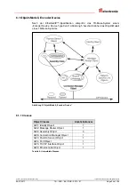
Page 23: ...m Encoder Device Device Type 0x22 Abbildung 5 beschreibt daher das Objekt Modell eines TR Mess Systems Abbildung 5 Objekt Modell Encoder Device 6 1 1 Classes Object Classes Anzahl Instances 0x01 Ident...

Page 24: ...tance Typ Name Beschreibung 1 Input Position 32 32 Bit Positionswert 100 Heartbeat Heartbeat 101 Input Position 64 64 Bit Positionswert Tabelle 5 bersicht I O Assembly Instanzen 6 1 3 I O Assembly Dat...

Page 25: ...en und entspricht einem Schreibdienst Hinweis Alle Set Attribute k nnen auch mittels Get_Attribute Services angesprochen werden Get Auf das Attribut kann mittels Get_Attribute Services zugegriffen wer...

Page 26: ...bindungsspezifische Attribute f r die Triggerung Transport Verbindungstyp etc Get 39 0x23 Position Sensor Object Enth lt alle Attribute f r die Programmierung der Mess System Parameter wie z B Skalier...

Page 27: ...reibung Default 1 Get Revision UINT Objekt Revisions Index 0x00 01 2 Get Max Instance UINT Max Instanznummer eines Objekts welches gegenw rtig in dieser Klassenebene erzeugt wurde 0x00 01 3 Get Number...

Page 28: ...pe UINT Bezeichnung des Ger tetyps 34 f r Encoder 0x00 22 0x03 Get Product Code UINT Herstellerbezo gener Produkt Code 0x00 31 0x04 Get Revision STRUCT of Ger te Revisions Index Major Revision USINT V...

Page 29: ...ehebbaren internen Ger tefehler an wird jedoch nicht in den Fehlerzustand versetzt keine Zustands nderung 10 Major Recoverable Fault TRUE Zeigt einen behebbaren internen Ger tefehler an und wird in de...

Page 30: ...ttribut gemeldeten Status mit dem Zustand der Modul Status LED Befindet sich das Mess System im Major Unrecoverable Fault Zustand ist keine Kommunikation mehr m glich Daher ist es nicht m glich einen...

Page 31: ...Fault Ger t hat einen Fehler wahrgenommen welcher nicht behebbar ist Tabelle 11 Ger te Zust nde F r das Identity Object integrierte Zustands nderungen Ereignis Beschreibung Power Applied Ger t eingesc...

Page 32: ...erviert 01 CRC Fehler Code space ROM Boot Ebene 02 CRC Fehler Code space ROM Applikation 03 CRC Fehler FLASH EEPROM 04 ung ltiger nichtfl chtiger Speicher fehlerhafte Konfiguration 05 ung ltiger nicht...

Page 33: ...Selbsttest Zustand 07 Standby Zustand 08 Betriebs Zustand 09 nicht spezifizierter Minor Recoverable Fehler erkannt 0A nicht spezifizierter Minor Unrecoverable Fehler erkannt 0B nicht spezifizierter Ma...

Page 34: ...ttribut Beschreibung Default 1 Get Revision UINT Objekt Revisions Index 0x00 01 2 Get Max Instance UINT Max Instanznummer eines Objekts welches gegenw rtig in dieser Klassenebene erzeugt wurde 0x00 01...

Page 35: ...00 02 0x00 04 0x00 06 0x00 67 0x00 F4 0x00 F5 0x00 F6 0x00 23 0x02 Get Number Available UINT Max Anzahl der unter st tzten Verbindungen 0x00 0A Tabelle 14 Message Router bersicht der Instanz Attribute...

Page 36: ...ion UINT Objekt Revisions Index 0x00 02 2 Get Max Instance UINT Max Instanznummer eines Objekts welches gegenw rtig in dieser Klassenebene erzeugt wurde 0x00 65 3 Get Number of Instances UINT Anzahl d...

Page 37: ...tributes Instance Attr ID Access NV Name Datentyp Beschreibung Default 1 0x03 Get NV Position 32 ARRAY of Byte Positionswert 32 Bit 0x04 Get NV Size UINT Liefert die Anzahl Bytes von Attribut 3 zur ck...

Page 38: ...l Type Attr ID Attr ID 3 7 4 3 2 Attribute 0x03 Position 64 Position 64 Instance 101 liefert den Positionswert des Mess Systems als 64 Bit Wert zur ck Positionswert 64 Bit COx 65 Byte 0 Byte 1 Byte 2...

Page 39: ...t Revision UINT Objekt Revisions Index 0x00 01 2 Get Max Instance UINT Max Instanznummer eines Objekts welches gegenw rtig in dieser Klassenebene erzeugt wurde 0x00 01 3 Get Number of Instances UINT A...

Page 40: ...NT Anzahl der abgelehnten For ward_Close Service Anfragen aufgrund anderer Gr nde 0x00 00 0x08 Get V Connection Timeouts UINT Gesamtanzahl der aufgetretenen Verbindungs Timeouts 0x00 00 Tabelle 18 Con...

Page 41: ...lt des entsprechenden Attributes zur ck 0x10 Set_Attribute_Single Modifiziert den Wert eines entsprechenden Attributes 7 6 2 Class Attributes Nr Access Name Datentyp Attribut Beschreibung Default 1 Ge...

Page 42: ...den Ger tetyp 0x00 02 Multi Turn Absolut Drehgeber 43 0x0C Set V Direction Counting Toggle BOOL Z hlrichtung des Positionswertes 0 Z hlrichtung steigend 44 0x64 Get NV Position Value ULINT Positionsw...

Page 43: ...s divisor 0x68 Preset Value 0x70 Accept Parameter Verbindungspfad Packed EPATH mit 8 Bit Klasse 0x20 0x23 0x24 0x01 0x30 0x02 Logical Type Class Class 23 Logical Type Instance Instance 1 Logical Type...

Page 44: ...lass 23 Logical Type Instance Instance 1 Logical Type Attr ID Attr ID 12 Damit dieses Attribut bernommen und dauerhaft gespeichert wird muss 0x70 Accept Parameter ausgef hrt werden 7 6 3 4 Attribute 0...

Page 45: ...ass bei einem Multi Turn Mess System der Quotient von Umdrehungen Z hler Umdrehungen Nenner eine 2er Potenz aus der Menge 20 21 22 212 1 2 4 4096 ist oder Sicherstellen dass sich Positionierungen im s...

Page 46: ...ert f r die Messl nge in Schritten ist von der Mess System Ausf hrung abh ngig und kann nach untenstehender Formel berechnet werden Da der Wert 0 bereits als Schritt gez hlt wird ist der Endwert Messl...

Page 47: ...Z hler Datentyp UDINT Access Set Get Untergrenze 1 Obergrenze 256000 Default 4096 Attr ID 0x67 Nenner Datentyp UDINT Access Set Get Untergrenze 1 Schritt Obergrenze 256000 Default 4096 Messl nge in Sc...

Page 48: ...er man passt die Mechanik bzw bersetzung entsprechend an Der Parameter Anzahl Schritte pro Umdrehung darf ebenfalls eine Kommazahl sein jedoch nicht die Messl nge in Schritten Das Ergebnis aus obiger...

Page 49: ...nik in Endlage bringen Den mechanisch zur ckgelegten Weg in mm vermessen Istposition des Mess Systems an der angeschlossenen Steuerung ablesen Annahme zur ckgelegter Weg 2000 mm Mess Sysem Istposition...

Page 50: ...reiches von 0 bis programmierte Messl nge in Schritten 1 Default 0 Presetwert Byte 0 Byte 1 Byte 2 Byte 3 Byte 4 Byte 5 Byte 6 Byte 7 CEx 65 2 7 bis 2 0 2 15 bis 2 8 2 23 bis 2 16 2 31 bis 2 24 COx 65...

Page 51: ...alle ge nderten Attribute dauerhaft gespeichert bzw die bernahme von ge nderten Werten f r die Instance Attribute 0x0C Z hlrichtung 0x65 Gesamtmessl nge in Schritten 0x66 Anzahl Umdrehungen Z hler und...

Page 52: ...Index 0x00 01 2 Get Max Instance UINT Max Instanznummer eines Objekts welches gegenw rtig in dieser Klassenebene erzeugt wurde 0x00 02 3 Get Number of Instances UINT Anzahl der gegenw rtig vorhandene...

Page 53: ...ntifikation der einzel nen Kommunikations ports 0x03 Get NV Link Object STRUCT of Path Length UINT Anzahl der 16 Bit Worte im folgenden Pfad 0x00 02 Link Path Padded EPATH Logisches Pfadsegment welche...

Page 54: ...kation der einzel nen Kommunikations ports 0x03 Get NV Link Object STRUCT of Path Length UINT Anzahl der 16 Bit Worte im folgenden Pfad 0x00 02 Link Path Padded EPATH Logisches Pfadsegment welches das...

Page 55: ...p wird der LOW Anteil zuerst geschrieben 0x0E Get_Attribute_Single Liefert den Inhalt des entsprechenden Attributes zur ck 0x10 Set_Attribute_Single Modifiziert den Wert eines entsprechenden Attribute...

Page 56: ...er 0xFF 57 0x04 Get Physical Link Object STRUCT of Pfad zum physika lischen Verbin dungsobjekt 58 Path size UINT Gr e des Pfades enth lt die Anzahl der 16 Bit Worte im Pfad 0x00 02 58 Path Padded EPAT...

Page 57: ...erviert 0 7 8 3 2 Attribute 0x02 Configuration Capability Das Configuration Capability Attribut ist bitkodiert und zeigt die vom Ger t unterst tzten optionalen Netzwerk Konfigurationsm glichkeiten an...

Page 58: ...t Klassencode 0xF6 Pfad Beschreibung 20 F6 24 01 20 8 Bit Klassen Segment Typ F6 Ethernet Link Object Klasse 24 8 Bit Instanz Segment Typ 01 Instanz 1 7 8 3 5 Attribute 0x05 Interface Configuration Da...

Page 59: ...wertet Config Control Schalter Aktion Beschreibung 0x00 0x00 oder 0xFF FLASH aktiv Konfiguration wird aus dem FLASH bezogen 0x00 andere Schalter aktiv IP Adresse 192 168 1 Schalterstellung Subnetzmask...

Page 60: ...ngle Service auf das Attribut 0x05 Interface Configuration bewirkt das Setzen der als Parameter bergebenen Werte Ist der Wert des Attributs 0x03 Configuration Control beim Ausf hren der Aktion 0x00 wi...

Page 61: ...Entsprechend dem Datentyp wird der LOW Anteil zuerst geschrieben 0x0E Get_Attribute_Single Liefert den Inhalt des entsprechenden Attributes zur ck 7 9 2 Class Attributes Nr Access Name Datentyp Attri...

Page 62: ...rt Bit Funktion Beschreibung 0 Verbindungsstatus 0 keine aktive Verbindung 1 aktive Verbindung siehe auch Bus Statusanzeige Seite 18 1 Halb Vollduplex 0 Halbduplex aktiv 1 Vollduplex aktiv 2 4 Erkennu...

Page 63: ...r ein Ger t Eing nge des Zielger tes empf ngt und Konfigurationsdaten in das Netzwerk versendet Eine Input Only Verbindung sendet keine Ausg nge es k nnen nur Eing nge empfangen werden Es k nnen aber...

Page 64: ...ility Bestandteil der Steuerungssoftware Das Programm ist geeignet f r die Installation auf einem PC mit WINDOWS Betriebssystem Der PC welcher als DHCP Server fungiert muss sich im selben Netz befinde...

Page 65: ...System startet zyklisch DHCP Anfragen welche mit Angabe der MAC Adresse in die Request History eingetragen werden 5 Einer der Eintr ge doppelklicken Die New Entry Dialog Box erlaubt folgende Eintragu...

Page 66: ...age dem Mess System zugewiesen Das Ergebnis dieser Zuweisung wird in die Request History eingetragen 6 ber den Button Disable BOOTP DHCP die IP Parameter in das FLASH abspeichern Die erfolgreiche Ausf...

Page 67: ...et Art Nr 490 00310 Kunststoff Koffer mit nachfolgenden Komponenten USB PC Adapter V4 Umsetzung USB RS485 USB Kabel 1 00 m Verbindungskabel zwischen PC Adapter und PC Flachbandkabel 1 30 m Verbindungs...

Page 68: ...h daraufhin mit den einstellbaren Parametern In der Registerkarte Ger tedaten k nnen die gew nschten IP Parameter eingestellt werden Die Abspeicherung der IP Parameter geschieht ber Men Ger t Daten an...

Page 69: ...erstellt werden k nnen die Empfangsdaten speichern k nnen 9 3 1 Vorgehensweise 1 Unter der Ordnerstruktur I O Configuration ein neues Modul anlegen und der Eintrag ETHERNET MODULE Generic Ethernet Mod...

Page 70: ...2017 3 Unter der Ordnerstruktur Controller Tags ein neuer Steuerungs Tag erstellen und folgende Einstellungen vornehmen Type Base Data_Type Message Scope angelegter Projektname zuweisen 4 Unter der O...

Page 71: ...but 0x64 Position Value aus dem Position Sensor Object 0x23 aus Message_Type CIP Generic Service Type gew nschter Service hier z B Get Attribute Single f r das Lesen eines einzelnen Attributes Service...

Page 72: ...ration ber Hardware Schalter siehe Seite 17 Konfiguration aus dem FLASH siehe Seite 57 Konfiguration ber DHCP siehe Seite 57 1 Hz Es wurden keine Verbindungen hergestellt aber eine IP Adresse wurde zu...

Page 73: ...den 05 Path destination unknown Der Pfad bezieht sich auf eine Objekt Klasse Instanz oder Strukturelement welcher dem Knoten nicht bekannt ist oder nicht enthalten ist 06 Partial transfer Nur ein Teil...

Page 74: ...tion failure Aufgrund eines Fehlers wurden die Attributdaten f r dieses Objekt nicht gespeichert 1A Routing failure request packet too large Das Service Anfragepaket im Pfad zum Ziel war zu gro f r di...

Page 75: ...wird vom Server nicht unterst tzt 25 Key Failure in path Das Schl sselsegment welches als erstes Segment im Pfad eingebunden wurde passt nicht zum Zielmodul Der objektspezifische Status zeigt den ent...

Page 76: ...en wiederholt auftritt muss das Mess System getauscht werden elektrische St rungen EMV Gegen elektrische St rungen helfen eventuell isolierende Flansche und Kupplungen aus Kunststoff sowie Kabel mit p...

Page 77: ...t Integer LINT 0xC5 Signed 64 Bit Integer USINT 0xC6 Unsigned 8 Bit Integer UINT 0xC7 Unsigned 16 Bit Integer UDINT 0xC8 Unsigned 32Bit Integer ULINT 0xC9 Unsigned 64 Bit Integer REAL 0xCA 32 Bit Floa...

Page 78: ...Anhang TR Electronic GmbH 2008 All Rights Reserved Printed in the Federal Republic of Germany Page 78 of 155 TR ECE BA DGB 0073 07 06 27 2017...

Page 79: ...Printed in the Federal Republic of Germany TR Electronic GmbH 2008 All Rights Reserved 06 27 2017 TR ECE BA DGB 0073 07 Page 79 of 155 User Manual C__ 65 EtherNet IP...

Page 80: ...c and photographic archiving and modification require the written content of the manufacturer Violations shall be subject to claims for damages Subject to modifications The right to make any changes i...

Page 81: ...licit Messaging exchange of information s 91 3 2 2 Implicit Messaging exchange of I O data 91 3 3 EtherNet IP Device Profiles 92 3 4 Vendor ID 92 3 5 Further information s 92 4 Installation Preparatio...

Page 82: ...s 118 7 6 Object 0x23 Position Sensor 119 7 6 1 Common Services 119 7 6 2 Class Attributes 119 7 6 3 Instance 1 Attributes 120 7 6 3 1 Attribute 0x02 Attribute List 121 7 6 3 2 Attribute 0x0B Position...

Page 83: ...Connection type 141 9 Commissioning Support 142 9 1 IP configuration via DHCP server 142 9 1 1 Prerequisite 142 9 1 2 Procedure 142 9 2 IP configuration with TRWinProg FLASH storage 145 9 2 1 Connecti...

Page 84: ...dex First release 11 27 08 00 New Chapter 8 Connection type page 141 12 17 08 01 Additional notes Parameter acceptance and saving 10 05 10 02 Modification of the warnings EDS file without revision ind...

Page 85: ...User Manual is supplementary to other documentation such as product datasheets dimensional drawings leaflets and the assembly instructions etc The User Manual may be included in the customer s specif...

Page 86: ...Access with Collision Detection CSMA CD Access Method and Physical Layer Specifications 16 RFC768 Defines the User Datagram Protocol UDP 17 RFC791 Defines the Internet Protocol IP 18 RFC792 Defines t...

Page 87: ...on Protocol dynamic assignment of an IP address DNS Domain Name System Name resolution into an IP address EDS Electronic Data Sheet EMC Electro Magnetic Compatibility Gateway Interconnect point betwee...

Page 88: ...ed 2 2 Additional instructions for proper use The measuring system is designed for operation in 100Base TX Fast Ethernet networks with max 100 Mbit s specified in ISO IEC 8802 3 Communication via Ethe...

Page 89: ...operation of the measurement system Prior to commencing work personnel working with the measurement system must have read and understood the assembly instructions in particular the chapter Basic safe...

Page 90: ...ion and maintenance of the EtherNet IP standard is regulated by the ODVA EtherNet IP along with ControlNet and DeviceNet belongs to the family of CIP based networks The CIP Common Industrial Protocol...

Page 91: ...TCP IP Stack Handling 3 2 1 Explicit Messaging exchange of information s Non time critical data transfers typically large packet size Information data exchanges are short lived explicit connections be...

Page 92: ...pe number 22hex was defined for EtherNet IP Encoders 3 4 Vendor ID The vendor IDs manufacturer s identifiers are assigned and administrated by the ODVA The TR Electronic Vendor ID for EtherNet IP is 1...

Page 93: ...ex capable on all ports IGMP Snooping limits multicast data traffic for the ports with associated IP multicast group IGMP Query Router or Switch with active IGMP function send queries periodically in...

Page 94: ...coded 1 11 27 V DC Voltage Supply 1 3 2 4 2 TRWinProg for service purposes only 3 GND 0V Voltage Supply 4 TRWinProg for service purposes only Shielded twisted pair cables must be used for the supply...

Page 95: ...s Net ID Host ID Table 1 Construction of the IPv4 address The Node address is adjusted by means of two HEX rotary switches which are read in only in the POWER ON momentum Additional adjustments during...

Page 96: ...odes The EDS file is integrated using the EtherNet IP network configuration tool to correctly configure or operate the measuring system The EDS file has the file name 04710022_TR_EIP_XXXXXX eds Downlo...

Page 97: ...ed The device has at least one established connection e g to the Message Router 1 Hz green red Self test Valid while the device is performing its power up testing 5 2 3 Error LED LED Status Cause Desc...

Page 98: ...f the device E g 00 03 12 04 00 60 5 3 2 IP Address So that an EtherNet IP device as a subscriber at the Industrial Ethernet can be controlled this device additionally needs an explicit IP Address in...

Page 99: ...ddress 3 Byte Host address Class B Net 2 Byte Net address 2 Byte Host address Class C Net 3 Byte Net address 1 Byte Host address Example Subnet mask IP Address 130 094 122 195 Net mask 255 255 255 224...

Page 100: ...consists of different variables attributes that describe the properties of this instance Different instances of a class have the same services the same behavior and the same variables attributes They...

Page 101: ...onds to an Encoder Device Device Type 0x22 Figure 5 therefore describes the Object Model of a TR measuring system Figure 5 Object Model Encoder Device 6 1 1 Classes Object Classes Number of Instances...

Page 102: ...Instance Type Name Description 1 Input Position 32 32 bit position value 100 Heartbeat Heartbeat 101 Input Position 64 64 bit position value Table 5 Overview I O Assembly Instances 6 1 3 I O Assembly...

Page 103: ...accessed by means of Set_Attribute services writing Note Set attributes can also be accessed by means of Get_Attribute services Get The attribute can be accessed by means of Get_Attribute services re...

Page 104: ...bject Contains connection specific attributes for triggering transport connection type etc Get 117 0x23 Position Sensor Object Contains all attributes for programming the measuring system parameter su...

Page 105: ...0x00 01 2 Get Max Instance UINT Maximum instance number of an object currently created in this class level of the device 0x00 01 3 Get Number of Instances UINT Number of object instances currently cr...

Page 106: ...of the device type 34 for Encoder 0x00 22 0x03 Get Product Code UINT Vendor specific product code 0x00 31 0x04 Get Revision STRUCT of Revision index of the device Major Revision USINT Version No 0x01...

Page 107: ...with itself which is thought to be unrecoverable The problem does not cause the device to go into one of the faulted states See Behavior section 10 Major Recoverable Fault TRUE Indicates the device d...

Page 108: ...rted by the Status Attribute with the state of the Module Status LED The measuring system is not able to communicate in the Major Unrecoverable Fault state Therefore it might not be able to report a M...

Page 109: ...states The Identity Object contains the following events Event Description Power Applied The device is powered up Passed Tests The device has successfully passed all self tests Activated The device s...

Page 110: ...ace ROM Boot section 02 Checksum or CRC error Code space ROM Application section 03 Checksum or CRC error NV FLASH EEPROM memory 04 Invalid non volatile NV memory Configuration bad 05 Invalid non vola...

Page 111: ...eactivated 06 Enter Self Test State 07 Enter Standby State 08 Enter Operational State 09 Non Specific Minor Recoverable Fault Detected 0A Non Specific Minor Unrecoverable Fault Detected 0B Non Specifi...

Page 112: ...of this object 0x00 01 2 Get Max Instance UINT Maximum instance number of an object currently created in this class level of the device 0x00 01 3 Get Number of Instances UINT Number of object instanc...

Page 113: ...0x00 04 0x00 06 0x00 67 0x00 F4 0x00 F5 0x00 F6 0x00 23 0x02 Get Number Available UINT Maximum number of connections supported 0x00 0A Table 14 Message Router Overview of the instance attributes 7 3 4...

Page 114: ...Maximum instance number of an object currently created in this class level of the device 0x00 65 3 Get Number of Instances UINT Number of object instances currently created at this class level of the...

Page 115: ...nce Attributes Instance Attr ID Access NV Name Data type Description Default 1 0x03 Get NV Position 32 ARRAY of Byte Position value 32 Bit 0x04 Get NV Size UINT Number of bytes in Attribute 3 0x00 04...

Page 116: ...nce 1 Logical Type Attr ID Attr ID 3 7 4 3 2 Attribute 0x03 Position 64 Position 64 Instance 101 returns the position value of the measuring system as 64 bit value Position value 64 Bit COx 65 Byte 0...

Page 117: ...INT Maximum instance number of an object currently created in this class level of the device 0x00 01 3 Get Number of Instances UINT Number of object instances currently created at this class level of...

Page 118: ...ts UINT Number of Forward_Close service requests which were rejected for reasons other than bad format 0x00 00 0x08 Get V Connection Timeouts UINT Total number of connection timeouts that have occurre...

Page 119: ...he contents of the specified attribute 0x10 Set_Attribute_Single Modifies the contents of the specified attribute 7 6 2 Class Attributes No Access Name Data type Attribute Description Default 1 Get Re...

Page 120: ...n Absolute Ro tary Encoder 121 0x0C Set V Direction Counting Toggle BOOL Counting direction of the position value 0 Counting direction increasing 122 0x64 Get NV Position Value ULINT Position value 64...

Page 121: ...sor 0x68 Preset Value 0x70 Accept Parameter Connection path Packed EPATH with 8 bit class 0x20 0x23 0x24 0x01 0x30 0x02 Logical Type Class Class 23 Logical Type Instance Instance 1 Logical Type Attr I...

Page 122: ...0x01 0x30 0x0C Logical Type Class Class 23 Logical Type Instance Instance 1 Logical Type Attr ID Attr ID 12 So that this attribute is accepted and saved permanently 0x70 Accept Parameter must be perfo...

Page 123: ...g system is lost Ensure that the quotient of Revolutions Numerator Revolutions Denominator for a multi turn measuring system is an exponent of 2 of the group 20 21 22 212 1 2 4 4096 or Ensure that eve...

Page 124: ...or the measurement length to be entered in steps is dependent on the measuring system version and can be calculated with the formula below As the value 0 is already counted as a step the end value mea...

Page 125: ...rator Data type UDINT Access Set Get Lower limit 1 Upper limit 256000 Default 4096 Attr ID 0x67 Divisor Data type UDINT Access Set Get Lower limit 1 step Upper limit 256000 Default 4096 Total measurin...

Page 126: ...or to adapt the mechanics or gearbox accordingly The parameter Steps per revolution may also be decimal number however the Total measuring range may not The result of the above formula must be rounded...

Page 127: ...ured to the end position Measure the mechanical distance covered in mm Read off the actual value of the measuring system from the controller connected Assumed Distance covered 2000 mm Measuring system...

Page 128: ...8 Data type ULINT Access Set Get Lower limit 0 Upper limit Value within the range from 0 to programmed measuring length in steps 1 Default 0 Preset value Byte 0 Byte 1 Byte 2 Byte 3 Byte 4 Byte 5 Byte...

Page 129: ...ttributes are stored permanently and the acceptance of changed values for the instance attributes 0x0C Direction Counting Toggle 0x65 Total Measuring Range 0x66 Number of Revolutions numerator and 0x6...

Page 130: ...ect currently created in this class level of the device 0x00 02 3 Get Number of Instances UINT Number of ports currently available 0x00 02 4 not implemented 5 not implemented 6 Get Maximum ID Number C...

Page 131: ...value to identify each communication port 0x03 Get NV Link Object STRUCT of Path Length UINT Number of 16 bit words in the following path 0x00 02 Link Path Padded EPATH Logical path segments that iden...

Page 132: ...lue to identify each communication port 0x03 Get NV Link Object STRUCT of Path Length UINT Number of 16 bit words in the following path 0x00 02 Link Path Padded EPATH Logical path segments that identi...

Page 133: ...ribute_Single Returns the contents of the specified attribute 0x10 Set_Attribute_Single Modifies the contents of the specified attribute 7 8 2 Class Attributes No Access Name Data type Attribute Descr...

Page 134: ...om DHCP if hard ware switches 0x00 or 0xFF 135 0x04 Get Physical Link Object STRUCT of Path to physical link object 136 Path size UINT Size of path number of 16 bit words in path 0x00 02 136 Path Padd...

Page 135: ...ibute 0x02 Configuration Capability The Configuration Capability attribute is a bitmap that indicates the device s support for optional network configuration capability Bit Function Description 0 BOOT...

Page 136: ...oints to an instance of the Ethernet Link Object class code 0xF6 Path Description 20 F6 24 01 20 8 Bit Class Segment Type F6 Ethernet Link Object Class 24 8 Bit Instance Segment Type 01 Instance 1 7 8...

Page 137: ...and is evaluated as follows Config Control Switch Action Description 0x00 0x00 or 0xFF FLASH active Configuration is obtained from the FLASH 0x00 other Switch active IP address 192 168 1 Switch posit...

Page 138: ...ied to attribute 0x05 the contents of the Interface Configuration will be set as new IP parameter If the value of the attribute 0x03 Configuration Control 0x00 when this action is performed the config...

Page 139: ...st 0x0E Get_Attribute_Single Returns the contents of the specified attribute 7 9 2 Class Attributes Nr Access Name Data type Attribute Description Default 1 Get Revision UINT Revision of this object 0...

Page 140: ...d as follows Bit Function Description 0 Link Status 0 Indicates an inactive link 1 Indicates an active link see also Bus status display page 96 1 Half Full Duplex 0 Half Duplex active 1 Full Duplex ac...

Page 141: ...cifies an independent connection where a device receives inputs from the target device and sends configuration data to the network An Input Only connection does not send outputs it only receives input...

Page 142: ...ram is suitable for the installation on a PC with WINDOWS operating system DHCP server and measuring system must be located in the same network segment 9 1 2 Procedure 1 Connect the measuring system w...

Page 143: ...uring system starts with DHCP requests which are registered into the Request History with the corresponding MAC address 5 Double click one of the entries The New Entry dialog allows you to enter all o...

Page 144: ...system with the next DHCP request The result of this assignment is registered into the Request History 6 Store IP parameters into the FLASH about the button Disable BOOTP DHCP This command is confirm...

Page 145: ...01 Programming set Order No 490 00310 Plastic case with the following components USB PC adapter V4 Conversion USB RS485 USB cable 1 00 m Connection cable between PC adapter and PC Flat ribbon cable 1...

Page 146: ...ine mode Hereupon the measuring system replies with the adjustable parameters In the tab Device data the desired IP parameters can be adjusted The storage of the IP parameters can be performed about m...

Page 147: ...be able to create variables to store receive data 9 3 1 Procedure 1 Create a new module under the folder structure I O Configuration and choose the entry ETHERNET MODULE Generic Ethernet Module 2 Per...

Page 148: ...27 2017 3 Create a new Controller Tag under the folder structure Controller Tags and perform the following adjustments Type Base Data_Type Message Scope choose the created project name 4 Create a new...

Page 149: ...tion Value from the Position Sensor Object 0x23 Message_Type CIP Generic Service Type desired service here e g Get Attribute Single to read a single attribute Service Code 0x0E is the code for the Get...

Page 150: ...Configuration via hardware switches see page 95 Configuration via FLASH see page 135 Configuration via DHCP see page 135 1 Hz No connections established but an IP address was obtained Try to read the...

Page 151: ...the processing node 05 Path destination unknown The path is referencing an object class instance or structure element that is not known or is not contained in the processing node 06 Partial transfer O...

Page 152: ...saved due to a failure during the attempt 1A Routing failure request packet too large The service request packet was too large for transmission on a network in the path to the destination The routing...

Page 153: ...is not supported by the server 25 Key Failure in path The Key Segment that was included as the first segment in the path does not match the destination module The object specific status indicates whi...

Page 154: ...If the error recurs despite these measures the measuring system must be replaced Electrical faults EMC Perhaps isolated flanges and couplings made of plastic help against electrical faults as well as...

Page 155: ...eger LINT 0xC5 Signed 64 Bit Integer USINT 0xC6 Unsigned 8 Bit Integer UINT 0xC7 Unsigned 16 Bit Integer UDINT 0xC8 Unsigned 32Bit Integer ULINT 0xC9 Unsigned 64 Bit Integer REAL 0xCA 32 Bit Floating...

Reviews: