Installation / Preparation for commissioning
TR-Electronic GmbH 2016, All Rights Reserved
Printed in the Federal Republic of Germany
Page 68 of 103
TR - ECE - BA - DGB - 0131 - 02
10/31/2018
4.3.2 Cable definition
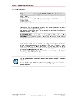
Signal
Line, e.g. 64-200-021: 2x2x0.25+3x0.14+2x0.5 mm
2
Data+ / Data–
(RS422+ / RS422–)
min. 0,25 mm
2
, twisted in pairs and shielded
Clock+ / Clock–
(RS422+ / RS422–)
The maximum cable length depends on the SSI clock frequency and cable quality and
should be conditioned to the following diagram.
Pay attention, that per meter cable with an additional delay-time t
D
(Data+/Data–) of
approx. 6ns must be calculated.
SSI clock frequency [kHz]
810
750
570
360
220
120
100
Line length [m]
approx. 12.5 approx. 25
approx. 50
approx. 100 approx. 200 approx. 400 approx. 500
A shielded data cable must be used to achieve high electromagnetic interference
stability. The shielding should be connected with low resistance to protective ground
using large shield clips
at both ends
. Only if the machine ground is heavily
contaminated with interference towards the control cabinet ground the shield should
be grounded
in the control cabinet only.
It is also important that the data- and clock-lines are routed separate from power
current carrying cables if at all possible.
The applicable standards and guidelines are to be observed to insure safe and stable
operation!
In particular, the applicable EMC directive and the shielding and grounding guidelines
must be observed!

