

Printed in the Federal Republic of Germany
TR-Electronic GmbH 2016, All Rights Reserved
10/31/2018
TR - ECE - BA - DGB - 0131 - 02
Page 79 of 103
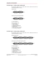
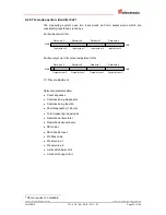
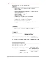
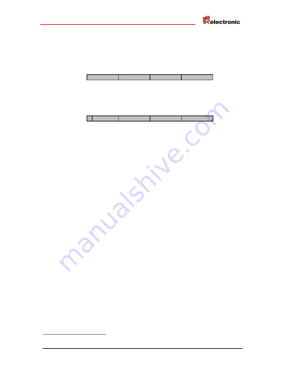
6.2.5 TR-mode position, identifier 0xF1
The measuring system uses two input words and two output words which are
consistently transferred via the bus.
Double input word ID x
Data byte 3
Data byte 2
Data byte 1
Data byte 0
LSB
MSB
Input byte x+0
Input byte x+1
Input byte x+2
Input byte x+3
Double output word for preset adjustment OD x
Data byte 3
Data byte 2
Data byte 1
Data byte 0
LSB
MSB
Output byte x+0
Output byte x+1
Output byte x+2
Output byte x+3
P
P = Preset adjustment
Relevant parameter data:
•
Count sequence
•
Commissioning diagnostics
•
Commissioning function
•
Short diagnostics (16 byte)
•
Total measuring range/units
•
Revolutions numerator
•
Revolutions denominator
•
SSI code
3
•
SSI data bit count
•
Profibus code
•
Preset value 1
•
Preset value 2
•
Limit switch lower limit
•
Limit switch upper limit
3
SSI on request, no standard


