Installation / Preparation for start-up
TR-Electronic GmbH 2010, All Rights Reserved
Printed in the Federal Republic of Germany
Page 140 of 183
TR - ELA - BA - DGB - 0016 - 04
01/20/2017
4 Installation / Preparation for start-up
The CANopen system is wired in bus topology with terminating resistors (121 ohms) at
the beginning and at the end of the bus line. If it is possible, drop lines should be
avoided. The cable is to be implemented as shielded twisted pair cable and should
have an impedance of 120 ohms and a resistance of 70 m
/m. The data transmission
is carried out about the signals CAN-H and CAN-L with a common GND as data
reference potential. Optionally also a 24 V supply voltage can be carried.
In a CANopen network max. 127 slaves can be connected. The measuring system
supports the Node-ID range from 1
…127. In case of LA/LP systems, by means of the
rotary switches only a value of max. 63 can be adjusted. The transmission rate can be
adjusted via switches or LSS/LMT protocol and supports the baud rates
●
10 kbit/s
●
20 kbit/s
●
50 kbit/s
●
100 kbit/s
●
125 kbit/s
●
250 kbit/s
●
500 kbit/s
●
800 kbit/s
●
1 Mbit/s
In case of LA/LP systems, by means of the rotary switches only the baud rates
20 kbit/s, 125 kbit/s, 500 kbit/s and 1 Mbit/s are supported, in case of LMP systems
the baud rate 10 kbit/s can be adjusted only by means of the LSS/LMT protocol.
The length of a CANopen network is depending on the transmission rate and is represented in the
following:
Cable cross section
10 kbit/s
20 kbit/s
50 kbit/s 100 kbit/s 125 kbit/s 250 kbit/s 500 kbit/s 800 kbit/s
1 Mbit/s
0.25 mm
2
– 0.34 mm
2
5000 m
2500 m
1000 m
ca. 600 m
500 m
250 m
100 m
50 m
25 m
The
-
ISO 11898,
-
the recommendations of the CiA DR 303-1
(CANopen cabling and connector pin assignment)
-
and other applicable standards and guidelines are to be observed to insure
safe and stable operation!
In particular, the applicable EMC directive and the shielding and grounding guidelines
must be observed!
4.1 Connection
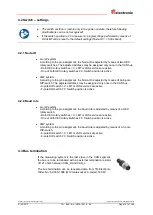
The connection can be made with device specific pin assignment which is enclosed
when the device is delivered.
For the supply shielded cables with twisted core pairs have to be used !


