Installation / Preparation for commissioning
TR-Electronic GmbH 2011, All Rights Reserved
Printed in the Federal Republic of Germany
Page 94 of 139
TR - ELE - BA - DGB - 0022 - 04
02/08/2016
6 Installation / Preparation for commissioning
6.1 Mounting
Three M4 threaded holes in the bottom of the LLB make it easy to mount the
device.
6.2 Alignment of the laser beam
Alignment of the laser beam is often difficult when the target is far away, as the laser
spot is not visible. An optional telescopic viewfinder is available which simplifies
alignment significantly. Please refer to chapter 10 Accessories
on page
138 for a
description of the viewfinder.
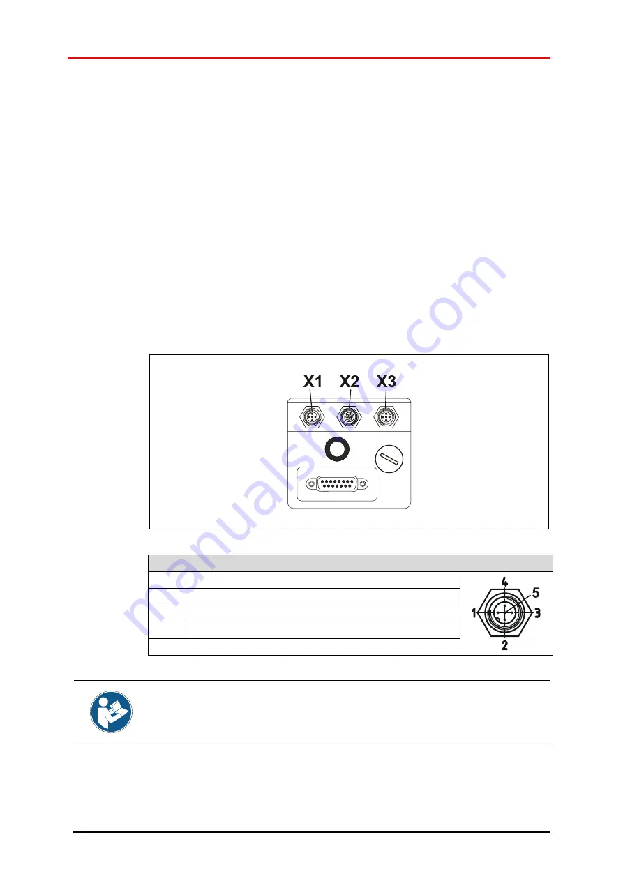
6.3 Supply voltage / Digital I/O
– connection
X3
M a l e c o n n e c t o r , (M12x1-5 pol. A-coded)
Pin 1
GND, Ground line and reference potential for pin 3/4/5
Pin 2
+13 V DC…+30 V DC, 0.6 A
Pin 3
Digital Output DOE, Open Drain
Pin 4
Digital Output DO1, Open Drain or Digital Input DI1
Pin 5
Digital Output DO2, Open Drain
For trouble-free operation use a separate power supply for the
LLB
.
For the supply voltage a cable cross section of min. 0.75 mm
2
is recommended.


