Printed in the Federal Republic of Germany
TR-Electronic GmbH 2018, All Rights Reserved
11/12/2019
TR - ELA - BA - DGB - 0027 - 03
Page 153 of 167
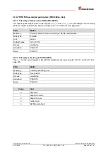
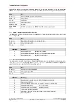
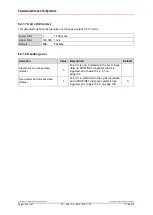
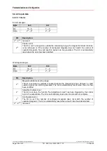
6.4.2 TR submodules Po Speed 1 to 1-30
6.4.2.1 Structure of the cyclic process data
Structure of input data, IO device -> master
Byte
Bit
Input data
X+0
2
8
-2
15
Error
Status
Submodules Pos. + Vel. 1 to Pos. +
Vel. 1 - 30
X+1
2
0
-2
7
Error
X+2
2
8
-2
15
Warnings
X+3
2
0
-2
7
Warnings
X+4
2
0
-2
7
Life cycle counter
X+5
2
0
-2
7
Number of parameterized magnets
X+6
2
24
-2
31
Position value
Magnet 1
Submodule: Pos. + Vel. 1
X+7
2
16
-2
23
Position value
X+8
2
8
-2
15
Position value
X+9
2
0
-2
7
Position value
X+10
2
8
-2
15
Speed
X+11
2
0
-2
7
Speed
X+12
2
24
-2
31
Position value
Magnet 2
Submodule: Pos. + Vel. 1 - 02
X+13
2
16
-2
23
Position value
X+14
2
8
-2
15
Position value
X+15
2
0
-2
7
Position value
X+16
2
8
-2
15
Speed
X+17
2
0
-2
7
Speed
…
…
…
…
X+180 2
24
-2
31
Position value
Magnet 30
Submodule: Pos. + Vel. 1 - 30
X+181 2
16
-2
23
Position value
X+182 2
8
-2
15
Position value
X+183 2
0
-2
7
Position value
X+184 2
8
-2
15
Speed
X+185 2
0
-2
7
Speed
Structure of output data, master -> IO device
Byte
Bit
Output data
X+0
2
0
-2
7
Control byte, preset adjustment
Set/save adjustment value
X+1
2
24
-2
31
Magnet no., adjustment execution
Bit-coded preselection of magnet
X+2
2
16
-2
23
Magnet no., adjustment execution
X+3
2
8
-2
15
Magnet no., adjustment execution
X+4
2
0
-2
7
Magnet no., adjustment execution
X+5
2
24
-2
31
Adjustment value
Adjustment value for the preselected
magnet
X+6
2
16
-2
23
Adjustment value
X+7
2
8
-2
15
Adjustment value
X+8
2
0
-2
7
Adjustment value
X+9
2
16
-2
23
Options
Reserve
X+10
2
8
-2
15
Options
X+11
2
0
-2
7
Options

