background image

Parameterization and configuration


 TR-Electronic GmbH 2011, All Rights Reserved 

Printed in the Federal Republic of Germany 

Page 92 of 131 

TR - ECE - BA - DGB - 0089 - 04 

02/03/2016 

7 Parameterization and configuration 


Parameterization 


Parameterization  means  providing  a  PROFIBUS-DP  slave  with  certain  information 
required for operation prior to commencing the cyclic exchange of process data. The 
measuring system requires e.g. data for Resolution, Count direction etc. 
 
Normally  the  configuration  program  provides  an  input  mask  for  the  PROFIBUS-DP 
master  with  which  the  user  can  enter  parameter  data  or  select  from  a  list.  The 
structure of the input mask is stored in the device master file. The number and type of 
the  parameter  to  be  entered  by  the  user  depends  on  the  choice  of  nominal 
configuration. 


The  configuration  described  as  follows  contains  configuration  and  parameter  data 
coded  in  their  bit  and  byte  positions.  This  information  is  e.g.  only  of  significance  in 
troubleshooting  or  with  bus  master  systems  for  which  this  information  has  to  be 
entered manually. 

 
Modern  configuration  tools  provide  an  equivalent  graphic  interface  for  this  purpose. 
Here  the  bit  and  byte  positions  are  automatically  managed  in  the  "background".  The 
configuration example on page 120 
illustrates this again.


Summary of Contents for PROFI BUS AE 70 Series

Page 1: ...GB _Zus tzliche Sicherheitshinweise _Installation _Inbetriebnahme _Konfiguration Parametrierung _St rungsbeseitigung und Diagnosem glichkeiten _Additional safety instructions _Installation _Commissio...

Page 2: ...ung bedarf der schriftlichen Genehmigung durch den Hersteller Zuwiderhandlungen verpflichten zu Schadenersatz nderungsvorbehalt Jegliche nderungen die dem technischen Fortschritt dienen vorbehalten Do...

Page 3: ...S DP RS485 Installation Inbetriebnahmevorbereitung 12 5 1 Kabelspezifikation 13 5 1 1 Kabeltyp LiYC11Y Datenkabel mit 14x0 25 2x0 50 mm2 13 5 1 2 Kabeltyp PROFIBUS ECOFAST Hybrid Cable mit 4x1 5 2x0 6...

Page 4: ...hwindigkeit 1 x U min 53 7 10 Konfigurationsbeispiel SIMATIC Manager V5 1 54 8 St rungsbeseitigung und Diagnosem glichkeiten 58 8 1 Verwendung der PROFIBUS Diagnose 58 8 1 1 Normdiagnose 58 8 1 1 1 St...

Page 5: ...ights Reserved 02 03 2016 TR ECE BA DGB 0089 04 Page 5 of 131 nderungs Index nderung Datum Index Erstausgabe 02 03 11 00 ATEX spezifische Anpassungen 24 10 11 01 ATEX spezifische Anpassungen 19 02 15...

Page 6: ...ation Parametrierung St rungsbeseitigung und Diagnosem glichkeiten Da die Dokumentation modular aufgebaut ist stellt dieses Handbuch eine Erg nzung zu anderen Dokumentationen wie z B Produktdatenbl tt...

Page 7: ...en und Mess System Software DP Dezentralized Periphery Dezentrale Peripherie DPM1 DP Master der Klasse 1 sind Controller eines DP Systems und der ihm zugeordneten DP Slaves Typischerweise handelt es s...

Page 8: ...e ten kann wenn die entsprechenden Vorsichtsma nahmen nicht getroffen werden bedeutet dass eine leichte K rperverletzung eintreten kann wenn die entsprechenden Vorsichtsma nahmen nicht getroffen werde...

Page 9: ...r einen sicheren Betrieb zwingend einzuhalten Zur bestimmungsgem en Verwendung geh rt auch das Beachten aller Hinweise aus diesem Handbuch das Beachten der Betriebsanleitung insbesondere das dort ent...

Page 10: ...Erweitert 32 768 Messbereich Standard 4 096 Umdrehungen Erweitert 256 000 Umdrehungen softwaretechnisch Ausgabecode Bin r Gray gekappter Gray Standardbaudraten 9 6 kBaud bis 12 MBaud Zykluszeit 250 s...

Page 11: ...ezielles Profil verabschiedet Das Profil beschreibt die Ankopplung von Dreh Winkel und Linear Encodern mit Singleturn oder Multiturn Aufl sung an DP Zwei Ger teklassen definieren Basisfunktionen und Z...

Page 12: ...Repeater Signalverst rker eingesetzt werden um die einzelnen Bussegmente zu verbinden Die bertragungsgeschwindigkeit ist beim PROFIBUS standardm ig im Bereich zwischen 9 6 kBit s und 12 Mbit s w hlba...

Page 13: ...nd mit diesem Kabel ausgestattet II 2G II 2D Parameter Beschreibung TR Artikel Nr 64 200 123X Leiter E Cu Litze blank Isolationswiderstand 20 MOhm km Leiterwiderstand 79 9 Ohm km Aderisolation PVC YI2...

Page 14: ...4 MHz maximal bei 16 MHz maximal 0 0030 dB m 0 0040 dB m 0 025 dB m 0 049 dB m Wellenwiderstand 150 10 bei 3 20 MHz Schleifenwiderstand 138 km Schirmwiderstand 15 km Kapazit t 30 pF m bei 1 kHz Leite...

Page 15: ...eine ger tespezifische Steckerbelegung in gedruckter Form beigelegt 5 3 Bus Terminierung Ist das Mess System der letzte Teilnehmer im PROFIBUS Segment ist der Bus durch Bus Abschluss Widerst nde abzus...

Page 16: ...Teilnehmer B II in den Bus eingebunden werden kann Wenn das Mess System als letzter Teilnehmer in den Bus eingebunden werden soll muss extern eine Br cke von TERM_A nach Bus_A_OUT und von TERM_B nach...

Page 17: ...ne eindeutige Adresse haben d h jede eingestellte Adresse darf nur einmal im PROFIBUS vergeben werden Je nach Ger teausf hrung ist die Adresse bereits fest durch das Mess System vorgegeben und wird au...

Page 18: ...er Busmaster am PROFIBUS DP angeschlossen sein Wenn sonst ein zus tzlicher Busmaster eingesetzt wird muss sichergestellt werden dass der Busmaster und PC PG die gleichen Baudrateneinstellungen aufweis...

Page 19: ...t werden Im Men Extras PG PC Schnittstelle einstellen den Zugangspunkt CP5512 PROFIBUS ausw hlen und im Eigenschaftsfenster die Option PG PC ist einziger Master am Bus markieren Die fehlerfreie Funkti...

Page 20: ...rgenommen Im Eingabefenster PROFIBUS Adresse vergeben kann jetzt die neue Adresse vergeben werden der Adressbereich umfasst die Adressen 1 bis 99 ber den Schalter OK wird die neue Adresse ohne R ckmel...

Page 21: ...s tzlich empfiehlt es sich nur einen DP Slave am Bus zu betreiben die Baudrate auf 187 5 kbit s zu setzen und m glichst kurze Zuleitungen zum DP Slave zu benutzen Zum Zeitpunkt der Adressvergabe muss...

Page 22: ...nnt k nnen unter Men Online Live List alle im Netz aktiven Ger te mit ihrer Adresse angezeigt werden Die eigentliche Adressvergabe wird ber das Men Online Slaveadresse setzen vorgenommen Hierf r muss...

Page 23: ...ON abzuschlie en Zur Kontrolle ob die neue Adresse bernommen wurde sollte das Men Online Live List ausgef hrt werden Hierf r muss das Symbol f r den Master im Konfigurationsfenster aktiv sein Die Adr...

Page 24: ...amen Traaab5n bmp und Traaab5s bmp die das Mess System zum einen im Normalbetrieb und zum anderen mit St rung zeigt Download TR09AAAB GSG www tr electronic de f TR ECE ID MUL 0010 PROFIBUS Konfigurato...

Page 25: ...ng m ssen der Ger tetyp die Format und L ngeninformationen sowie die Anzahl der Ein und Ausg nge bereinstimmen Der Benutzer erh lt dadurch einen zuverl ssigen Schutz gegen Parametrierungsfehler Konnte...

Page 26: ...die der Anwender die Parameterdaten eingeben oder aus Listen ausw hlen kann Die Struktur der Eingabemaske ist in der Ger testammdatei hinterlegt Anzahl und Art der vom Anwender einzugebenden Paramete...

Page 27: ...ie entsprechenden Kennungen einzutragen hat Da das Mess System mehrere m gliche Konfigurationen unterst tzt ist abh ngig von der gew nschten Soll Konfiguration die einzugebende Kennung voreingestellt...

Page 28: ...odus Skalierungsfunktion Schritte Umdrehung Messl nge in Schritten 32 Bit IN 32 Bit OUT TR Mode Position Seite 35 Z hlrichtung Diagnose Meldemodus Kurze Diagnose Messl nge in Schritten Umdrehungen Z h...

Page 29: ...Konfigurationsdaten siehe Hinweis auf Seite 26 Ger te Klasse 1 0xD0 1 Wort Eingangsdaten f r Positionswert konsistent DDLM_Chk_Cfg Byte 1 Bit 7 6 5 4 3 0 Data 1 1 01 0 D 0 Konsistenz Wort Format Eing...

Page 30: ...7 20 Data_Exchange Positionsdaten Konfigurationsdaten siehe Hinweis auf Seite 26 Ger te Klasse 1 0xD1 1 Doppelwort Eingangsdaten f r Positionswert konsistent DDLM_Chk_Cfg Byte 1 Bit 7 6 5 4 3 0 Data 1...

Page 31: ...2 Bit 15 8 7 0 Data 215 28 27 20 Data_Exchange Positionsdaten Format f r Preset Justagewert Beschreibung der Funktion siehe Seite 43 Ausgangswort AWx Byte 1 2 Bit 15 14 8 7 0 Data 0 1 214 28 27 20 Pr...

Page 32: ...inn drehend X steigende Positions werte gegen den Uhr zeigersinn drehend 44 1 Klasse 2 Funktionalit t Nein Ja X 44 2 Diagnose Meldemodus ausgeschaltet X eingeschaltet 44 3 Skalierungsfunktion ausgesch...

Page 33: ...31 224 223 216 215 28 27 20 Data_Exchange Positionsdaten Format f r Preset Justagewert Beschreibung der Funktion siehe Seite 43 Ausgangsdoppelwort ADx Byte 1 2 3 4 Bit 31 30 24 23 16 15 8 7 0 Data 0 1...

Page 34: ...inn drehend X steigende Positions werte gegen den Uhr zeigersinn drehend 44 1 Klasse 2 Funktionalit t Nein Ja X 44 2 Diagnose Meldemodus ausgeschaltet X eingeschaltet 44 3 Skalierungsfunktion ausgesch...

Page 35: ...nsdaten Format f r Preset Justagewert Beschreibung der Funktion siehe Seite 43 Ausgangsdoppelwort ADx Byte 1 2 3 4 Bit 31 30 24 23 16 15 8 7 0 Data 0 1 230 224 223 216 215 28 27 20 Preset Ausf hrung P...

Page 36: ...d32 15 18 Seite 37 Seite 50 Umdrehungen Nenner unsigned16 19 20 Seite 37 Seite 50 Code SSI Schnittstelle unsigned8 21 X Code PROFIBUS Schnittstelle unsigned8 22 Seite 38 Seite 53 Preset 1 unsigned32 2...

Page 37: ...tet mit Status 0 0 0 0 0 0 1 0 Eingeschaltet mit Status 0 0 0 0 0 0 1 1 Zugeh rige Betriebsparameter zur Skalierung mit Getriebefunktion Beschreibung siehe Seite 50 DDLM_Set_Prm unsigned32 Byte 11 12...

Page 38: ...Data 27 26 25 24 23 22 21 20 Gray Code 0 0 0 0 0 0 0 0 Bin r Code Default 0 0 0 0 0 0 0 1 Gray gekappt 0 0 0 0 0 0 1 0 Betriebsparameter Unterer Endschalter Oberer Endschalter Beschreibung siehe Seite...

Page 39: ...ustagewert Beschreibung der Funktion siehe Seite 43 Ausgangsdoppelwort ADx Byte 1 2 3 4 Bit 31 30 24 23 16 15 8 7 0 Data 0 1 230 224 223 216 215 28 27 20 Preset Ausf hrung Preset Justagewert Konfigura...

Page 40: ...50 Umdrehungen Nenner unsigned16 19 20 Seite 41 Seite 50 Code SSI Schnittstelle unsigned8 21 X Code PROFIBUS Schnittstelle unsigned8 22 Seite 42 Seite 53 Preset 1 unsigned32 23 26 X Preset 2 unsigned...

Page 41: ...tet mit Status 0 0 0 0 0 0 1 0 Eingeschaltet mit Status 0 0 0 0 0 0 1 1 Zugeh rige Betriebsparameter zur Skalierung mit Getriebefunktion Beschreibung siehe Seite 50 DDLM_Set_Prm unsigned32 Byte 11 12...

Page 42: ...de Default 0 0 0 0 0 0 0 1 Gray gekappt 0 0 0 0 0 0 1 0 Betriebsparameter Unterer Endschalter Oberer Endschalter Beschreibung siehe Seite 53 DDLM_Set_Prm unsigned32 Byte 31 32 33 34 Bit 31 24 23 16 15...

Page 43: ...ann muss der Betriebsparameter Skalierungsfunktion eingeschaltet sein TR Modes Inbetriebnahmefunktion eingeschaltet mit Status Z hlrichtung und Preset Justage k nnen nicht gleichzeitig ausgef hrt werd...

Page 44: ...s System Anflanschung 7 9 2 Klasse 2 Funktionalit t Verf gbarkeit PNO CLASS1 16 32 PNO CLASS 2 16 32 X TR Mode Position TR Mode Position U Min nicht unterst tzt Seite 31 33 nicht unterst tzt nicht unt...

Page 45: ...25 231 Preset Justage ber Steuerbit 231 Justage anfordern Eingeschaltet mit Status siehe auch Hinweis auf Seite 43 Positionsausgabe auf den Bits 20 224 mit Statusbits 225 231 Preset Justage ber Steuer...

Page 46: ...Blick auf die Welle 1 Z hlrichtung entgegen dem Uhrzeigersinn Blick auf die Welle 29 Teach In Fahrweg bernehmen 0 wird nicht unterst tzt 1 wird nicht unterst tzt 30 Teach In Start 0 wird nicht unterst...

Page 47: ...wird nun wieder ausgegeben Preset Justage M Master Status Steuerbits Datenbits S Slave Bit 31 30 29 28 27 26 25 24 23 22 21 20 19 18 17 16 15 14 13 12 11 10 9 8 7 6 5 4 3 2 1 0 M S 1 0 0 0 0 0 0 Prese...

Page 48: ...Skalierungsparameter PNO CLASS 2 Maximale Schrittzahl pro Umdrehung 8192 Gr ere Schrittzahlen sind nur ber die TR Modes m glich Sind die Skalierungsparameter ber die Skalierungsfunktion freigeschalte...

Page 49: ...en dass die Parameter Messl nge in Schritten und Anzahl Schritte pro Umdrehung so gew hlt werden dass der Quotient aus beiden Parametern eine Zweierpotenz ist Ist dies nicht gegeben korrigiert das Mes...

Page 50: ...l sung des Mess Systems ver ndert werden Das Mess System unterst tzt die Getriebefunktion f r Rundachsen Dies bedeutet dass die Anzahl Schritte pro Umdrehung1 und der Quotient von Umdrehungen Z hler U...

Page 51: ...die entsprechende Kommanzahl m glicherweise nur ann hernd dargestellt werden Die sich ergebende kleine Ungenauigkeit wird bei echten Rundachsenanwendungen Endlos Anwendungen in eine Richtung fahrend...

Page 52: ...erfassende Mechanik in Endlage bringen Den mechanisch zur ckgelegten Weg in mm vermessen Istposition des Mess Systems an der angeschlossenen Steuerung ablesen Annahme zur ckgelegter Weg 2000 mm Mess S...

Page 53: ...tion Seite 45 dem Master ber ein Bit mitteilen ob sich der Istwert innerhalb der Grenzen befindet Endschalterbit 0 Prozess Istwert unterer Softwareendschalter oder Prozess Istwert oberer Softwareendsc...

Page 54: ...BA DGB 0089 04 02 03 2016 7 10 Konfigurationsbeispiel SIMATIC Manager V5 1 F r das Konfigurationsbeispiel wird vorausgesetzt dass die Hardwarekonfiguration bereits vorgenommen wurde Als CPU wird die...

Page 55: ...ntrag der GSD Datei lautet TR CE58_65M DP V1 Unter diesem Eintrag reihen sich die einzelnen Konfigurationsm glichkeiten an PNO Class 1 16 Bit siehe Seite 29 PNO Class 1 32 Bit siehe Seite 30 PNO Class...

Page 56: ...ral Republic of Germany Page 56 of 131 TR ECE BA DGB 0089 04 02 03 2016 Mess System an das Mastersystem Drag Drop anbinden Mit Anbindung des Mess Systems an das Mastersystem k nnen die Netzeinstellung...

Page 57: ...H 2011 All Rights Reserved 02 03 2016 TR ECE BA DGB 0089 04 Page 57 of 131 Gew nschte Konfiguration aus dem Katalog auf den Steckplatz bertragen Drag Drop Das Mess System Symbol muss aktiv sein Parame...

Page 58: ...ein Teilnehmer in der bersichtsdiagnose als gest rt gemeldet kann der Host weitere Daten vom Master anfordern Slavediagnose die dann eine detailliertere Auswertung ber die Gr nde der St rung zulassen...

Page 59: ...ete Konfigurationskennung en wurde n vom Slave abgelehnt Bit 1 Station_Not_Ready Slave ist nicht zum Austausch zyklischer Daten bereit Bit 0 Station_Non_Existent Der Slave wurde projektiert ist aber a...

Page 60: ...erforderlich dass bei gleichzeitigem Zugriff mehrerer Master deren Konfigurations und Parametrierinformation exakt bereinstimmt 8 1 1 5 Herstellerkennung Normdiagnose Byte 5 6 In die Bytes tr gt der S...

Page 61: ...ebs Status 1 2 TR Byte 10 Encodertyp 1 2 TR Byte 11 14 Encoderaufl sung in Schritten pro Umdrehung rotatorisch Encoderaufl sung in Mess Schritten Linear 1 2 TR Byte 15 16 Anzahl aufl sbare Umdrehungen...

Page 62: ...eutung 00 Singleturn Absolut Encoder rotatorisch 01 Multiturn Absolut Encoder rotatorisch weitere Codes siehe Encoderprofil 8 1 2 4 Singleturn Aufl sung Erweiterte Diagnose Byte 11 14 ber die Diagnose...

Page 63: ...Licht Kontrollreserve Nicht erreicht Erreicht Bit 3 CPU Watchdog Status OK Reset ausgef hrt Bit 4 Betriebszeitwarnung Nein Ja Bit 5 15 Batterieladung OK Zu niedrig 8 1 2 9 Unterst tzte Warnungen Erwei...

Page 64: ...r nach jeder Parametrierung oder wenn ein Fehler gemeldet werden muss jedoch nicht wenn alles in Ordnung ist und sich nur der Z hler ge ndert hat Daher wird bei der Online Diagnose immer der Stand von...

Page 65: ...ROFIBUS so nicht m glich Diese Funktion ist nur bei eingeschalteter Commissioning Diagnostic Funktion gew hrleistet 8 2 Sonstige St rungen St rung Ursache Abhilfe Positionsspr nge des Mess Systems sta...

Page 66: ...St rungsbeseitigung und Diagnosem glichkeiten TR Electronic GmbH 2011 All Rights Reserved Printed in the Federal Republic of Germany Page 66 of 131 TR ECE BA DGB 0089 04 02 03 2016...

Page 67: ...Printed in the Federal Republic of Germany TR Electronic GmbH 2011 All Rights Reserved 02 03 2016 TR ECE BA DGB 0089 04 Page 67 of 131 Programming Manual AE_ 70 PROFIBUS DP...

Page 68: ...e the written content of the manufacturer Violations shall be subject to claims for damages Subject to modifications The right to make any changes in the interest of technical progress is reserved Doc...

Page 69: ...IBUS DP RS485 Installation Pre commissioning 78 5 1 Cable specification 79 5 1 1 Cable type LiYC11Y data cable with 14x0 25 2x0 50 mm2 79 5 1 2 Cable type PROFIBUS ECOFAST Hybrid Cable with 4x1 5 2x0...

Page 70: ...119 7 10 Configuration example SIMATIC Manager V5 3 120 8 Troubleshooting and diagnosis options 124 8 1 Use of the PROFIBUS diagnosis 124 8 1 1 Standard diagnosis 124 8 1 1 1 Station status 1 125 8 1...

Page 71: ...ights Reserved 02 03 2016 TR ECE BA DGB 0089 04 Page 71 of 131 Revision index Revision Date Index First release 03 02 11 00 ATEX specific modifications 10 24 11 01 ATEX specific modifications 02 19 15...

Page 72: ...sioning Configuration Parameterization Troubleshooting and diagnostic options As the documentation is arranged in a modular structure this manual is supplementary to other documentation such as produc...

Page 73: ...measuring system software DP Decentralized Periphery DPM1 DP Master of Class 1 This is a central controller that cyclically exchanges information with the distributed stations slaves at a specified me...

Page 74: ...nd instructions means that death or serious injury could occur if the stated pre cautions are not met means that minor injuries can occur if the stated precautions are not met means that damage to pro...

Page 75: ...the PROFIBUS User Organization are always to be observed in order to ensure safe operation Proper use also includes observing all instructions in this manual observing the operating instruction The S...

Page 76: ...2 Expanded 32 768 Measurement range Standard 4 096 revolutions Expanded 256 000 revolutions software solution Output code Binary Gray shifted Gray Standard Baud rates 9 6 kBaud to 12 MBaud Cycle time...

Page 77: ...plemented a special profile for encoders The profile describes the connection of rotary angular and linear encoders with single turn or multi turn resolution to the DP Two device classes define the ba...

Page 78: ...to be used with more than 32 subscribers or to expand the network scope in order to connect the various bus segments The PROFIBUS transmission speed may be set between 9 6 kBit s and 12 Mbit s and is...

Page 79: ...ipped with this cable II 2G II 2D Parameter Description TR Order No 64 200 123X Conductor E Cu stranded wire uninsulated Insulation resistance 20 Mohm km Conductor resistance 79 9 ohm km Conductor ins...

Page 80: ...MHz maximal 0 0030 dB m 0 0040 dB m 0 025 dB m 0 049 dB m Wave impedance 150 10 at 3 20 MHz Loop resistance 138 km Shielding resistance 15 km Capacity 30 pF m at 1 kHz Conductor cross section power w...

Page 81: ...device specific pin assignment in printed form is enclosed 5 3 Bus termination If the measuring system is the last slave in the PROFIBUS segment the bus is to be terminated with bus termination resis...

Page 82: ...ernal wiring it is defined that this device type may be connected selectively between two slaves B I or as last slave B II into the bus If the measuring system is to be connected as last slave into th...

Page 83: ...ave a unique address for communication i e each adjusted address may be assigned only once in the PROFIBUS Depending upon type of device the address is already pre adjusted fixed and is noted on the n...

Page 84: ...ment no further bus master may be connected at the PROFIBUS DP If otherwise an additional bus master is used it must be guaranteed that the bus master and PC PG operate with the same baud rate the DP...

Page 85: ...manager can be started Select in the menu Options Set PG PC Interface the access point CP5512 PROFIBUS and mark the option PG PC is the only master on the bus in the properties window The error free...

Page 86: ...BUS Address Now in the input window Assign PROFIBUS Address the new address can be assigned the address range includes the addresses 1 to 99 By means of button OK the new address is stored permanently...

Page 87: ...cher DPM2 master Generally it is recommended to operate only one DP slave at the bus to set the baud rate to 187 5 kbit s and to use short connecting cables to the DP slave During address assignment t...

Page 88: ...er menu Online Live List all in the net accessible devices with their address can be displayed The real address assignment is performed by means of menu Online Set Slave Address For this purpose the s...

Page 89: ...re must be finished with POWER OFF ON For checking purposes whether the new address was set menu Online Live List should be executed For this purpose the symbol for the master must be active in the co...

Page 90: ...th the names Traaab5n bmp and Traaab5s bmp which show the measuring system in normal operation as well as with a fault Download TR09AAAB GSE www tr electronic de f TR ECE ID MUL 0010 Figure 7 GSD for...

Page 91: ...ration The device type the format and length information as well as the number of inputs and outputs must agree in this check The user is therefore reliably protected against parameterization errors I...

Page 92: ...ster with which the user can enter parameter data or select from a list The structure of the input mask is stored in the device master file The number and type of the parameter to be entered by the us...

Page 93: ...the corresponding identifiers As the measuring system supports several possible configurations the identifier to be entered is preset dependent on the required nominal configuration so that only the...

Page 94: ...Commissioning diagnostics Scaling function Steps per revolution Total measuring range 32 bit IN 32 bit OUT TR Mode Position Page 101 Count direction Commissioning diagnostics Short Diagnostics Total...

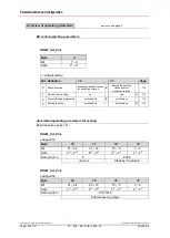
Page 95: ...tion data Configuration data see note on page 92 Device Class 1 0xD0 1 word input data for position value consistent DDLM_Chk_Cfg Byte 1 Bit 7 6 5 4 3 0 Data 1 1 01 0 D 0 Consistency Word format Input...

Page 96: ...6 215 28 27 20 Data_Exchange Position data Configuration data see note on page 92 Device Class 1 0xD1 1 double word input data for position value consistent DDLM_Chk_Cfg Byte 1 Bit 7 6 5 4 3 0 Data 1...

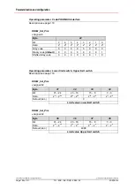
Page 97: ...Byte 1 2 Bit 15 8 7 0 Data 215 28 27 20 Data_Exchange Position data Format for preset adjustment value description of the function see page 109 Output word OWx Byte 1 2 Bit 15 14 8 7 0 Data 0 1 214 2...

Page 98: ...clockwise rotation X ascending position values counter clockwise rotation 110 1 Class 2 Functionality no yes X 110 2 Commissioning diagnostics switched off X switched on 110 3 Scaling function switche...

Page 99: ...Data 231 224 223 216 215 28 27 20 Data_Exchange Position data Format for preset adjustment value description of the function see page 109 Output double word ODx Byte 1 2 3 4 Bit 31 30 24 23 16 15 8 7...

Page 100: ...clockwise rotation X ascending position values counter clockwise rotation 110 1 Class 2 Functionality no yes X 110 2 Commissioning diagnostics switched off X switched on 110 3 Scaling function switch...

Page 101: ...ion data Format for preset adjustment value description of the function see page 109 Output double word ODx Byte 1 2 3 4 Bit 31 30 24 23 16 15 8 7 0 Data 0 1 230 224 223 216 215 28 27 20 Preset execut...

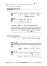
Page 102: ...ons numerator unsigned32 15 18 page 103 page 116 Revolutions denominator unsigned16 19 20 page 103 page 116 Code SSI Interface unsigned8 21 X Code PROFIBUS Interface unsigned8 22 page 104 page 119 Pre...

Page 103: ...status 0 0 0 0 0 0 1 0 Enabled with status 0 0 0 0 0 0 1 1 Associated operating parameters for scaling with gearbox function Description see page 116 DDLM_Set_Prm unsigned32 Byte 11 12 13 14 Bit 31 24...

Page 104: ...27 26 25 24 23 22 21 20 Gray code 0 0 0 0 0 0 0 0 Binary code default 0 0 0 0 0 0 0 1 Shifted Gray code 0 0 0 0 0 0 1 0 Operating parameter Lower limit switch Upper limit switch Description see page 1...

Page 105: ...ment value description of the function see page 109 Output double word ODx Byte 1 2 3 4 Bit 31 30 24 23 16 15 8 7 0 Data 0 1 230 224 223 216 215 28 27 20 Preset execution Preset adjustment value Confi...

Page 106: ...e 107 page 116 Revolutions denominator unsigned16 19 20 page 107 page 116 Code SSI Interface unsigned8 21 X Code PROFIBUS Interface unsigned8 22 page 108 page 119 Preset 1 unsigned32 23 26 X Preset 2...

Page 107: ...status 0 0 0 0 0 0 1 0 Enabled with status 0 0 0 0 0 0 1 1 Associated operating parameters for scaling with gearbox function Description see page 116 DDLM_Set_Prm unsigned32 Byte 11 12 13 14 Bit 31 24...

Page 108: ...de default 0 0 0 0 0 0 0 1 Shifted Gray code 0 0 0 0 0 0 1 0 Operating parameter Lower limit switch Upper limit switch Description see page 119 DDLM_Set_Prm unsigned32 Byte 31 32 33 34 Bit 31 24 23 16...

Page 109: ...n PNO CLASS 2 configurations the operating parameter Scaling function must be switched on TR Modes Teach In function enabled with status Count direction and Preset adjustment can not be executed at th...

Page 110: ...ew onto the measuring system flange 7 9 2 Class 2 Functionality Availability PNO CLASS1 16 32 PNO CLASS2 16 32 X TR Mode Position TR Mode Position Rpm not supported page 97 99 not supported not suppor...

Page 111: ...rol bit 231 Adjustment requested Enabled with status see also notice on page 109 Position output with the bits 20 224 and status bits 225 231 Preset adjustment via control bit 231 Adjustment requested...

Page 112: ...the moment 0 Counting direction cw with view on the shaft 1 Counting direction ccw with view on the shaft 29 Teach In takeover drive distance 0 not supported 1 not supported 30 Start Teach In 0 not s...

Page 113: ...l value is now output again Preset adjustment M Master Status Control bits Data bits S Slave Bit 31 30 29 28 27 26 25 24 23 22 21 20 19 18 17 16 15 14 13 12 11 10 9 8 7 6 5 4 3 2 1 0 M S 1 0 0 0 0 0 0...

Page 114: ...ter PNO CLASS 2 Maximum steps per revolution 8192 If higher resolutions are required one of the TR Modes must be used If the scaling parameters are activated with the Scaling function the physical res...

Page 115: ...that the parameters Total measuring range and Steps per revolution are selected such that the quotient of the two parameters is an exponent of 2 If this is not the case the measuring system corrects...

Page 116: ...e the physical resolution of the measuring system The measuring system supports the gearbox function for round axes This means that the Steps per revolution2 and the quotient of Revolutions numerator...

Page 117: ...o reduce these accordingly If this is not possible it may only be possible to represent the decimal number affected approximately The resulting minor inaccuracy accumulates for real round axis applica...

Page 118: ...hanics to be measured to the end position Measure the mechanical distance covered in mm Read off the actual value of the measuring system from the controller connected Assumed Distance covered 2000 mm...

Page 119: ...measuring system can inform the master via a bit whether the actual value is within the limits Limit switch bit 0 Process actual value lower limit switch or Process actual value upper limit switch Li...

Page 120: ...f 131 TR ECE BA DGB 0089 04 02 03 2016 7 10 Configuration example SIMATIC Manager V5 3 For the configuration example it is assumed that the hardware configuration has already taken place The CPU315 2...

Page 121: ...Devices Encoder TR ELECTRONIC The entry for the GSD file is TR CE58_65M DP V1 The sequence of the respective configuration options is given in this entry PNO Class 1 16 bit see page 95 PNO Class 1 32...

Page 122: ...rinted in the Federal Republic of Germany Page 122 of 131 TR ECE BA DGB 0089 04 02 03 2016 Connect measuring system to the master system drag drop Once the measuring system is connected to the master...

Page 123: ...H 2011 All Rights Reserved 02 03 2016 TR ECE BA DGB 0089 04 Page 123 of 131 Transfer the required configuration from the catalogue to the slot drag drop The measuring system symbol must be active Perf...

Page 124: ...mary diagnosis the host can request further data from the master slave diagnosis which then allows a detailed evaluation of the reasons for the fault The reports obtained in this way can be generated...

Page 125: ...er s sent from the master has have been rejected by the slave bit 1 Station_Not_Ready Slave is not ready to exchange cyclical data bit 0 Station_Non_Existent The slave has been projected but is not av...

Page 126: ...erative that in the case of simultaneous access of several masters their configuration and parameterization information exactly matches 8 1 1 5 Manufacturer s identifier Standard diagnosis byte 5 6 Th...

Page 127: ...TR byte 10 Encoder type 1 2 TR byte 11 14 Encoder resolution in steps per revolution rotational Encoder resolution in measurement steps linear 1 2 TR byte 15 16 Number of resolvable revolutions 1 2 T...

Page 128: ...cance 00 Single turn absolute encoder rotational 01 Multi turn absolute encoder rotational for further codes see encoder profile 8 1 2 4 Single turn resolution Extended diagnosis bytes 11 14 The hardw...

Page 129: ...ntrol reserve not achieved achieved bit 3 CPU watchdog status OK reset performed bit 4 Operating time warning no yes bit 5 15 Battery charge OK too low 8 1 2 9 Warnings supported Extended diagnosis by...

Page 130: ...ding is sent but only after each parameterization or if a error has to be reported however not if everything is working correctly and only the counter has changed The state of the last parameterizatio...

Page 131: ...the user via the PROFIBUS is therefore not possible This function is only guaranteed if the commissioning diagnostic function is activated 8 2 Other faults Fault Cause Remedy Position skips of the me...

Reviews: