background image


TRAC ABOUT, INC. 


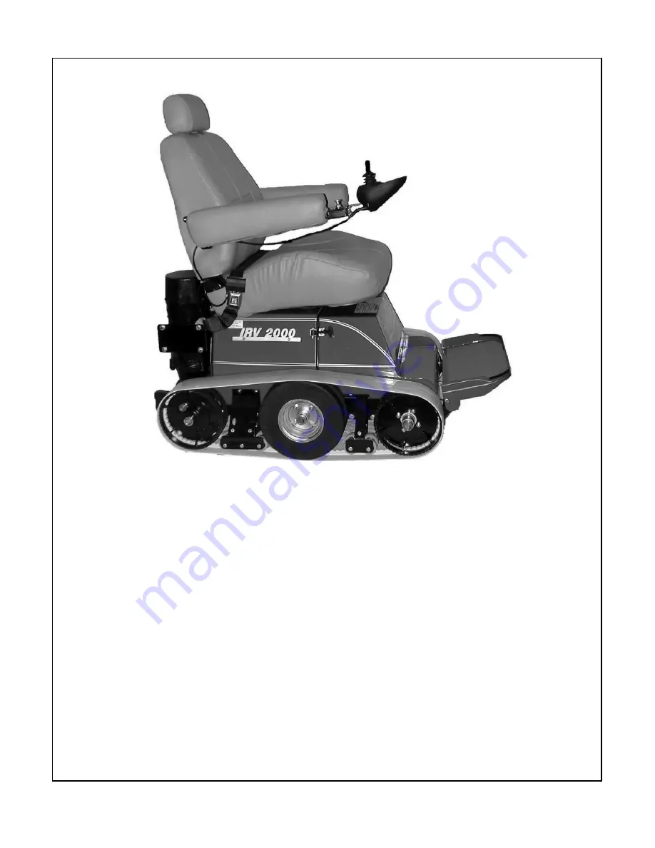
IRV2000


OWNERS MANUAL 


Trac About, Inc. 

Newton, Kansas 

316-283-5660 

Summary of Contents for IRV2000

Page 1: ...TRAC ABOUT INC IRV2000 OWNERS MANUAL Trac About Inc Newton Kansas 316 283 5660 ...

Page 2: ...ion and low center of gravity make the machine extremely safe Outdoors the IRV2000 is unsurpassed for its ability to take you over rough terrain through mud snow and seaside sand It can cross curbs and other obstructions up to 4 5 inches if you cross them at a slight angle THE IRV2000 WILL NOT GO UP A STAIRWAY To get the most enjoyment and use of your IRV2000 you really should read the manual befo...

Page 3: ...ve access to the INTERNET or if I need more help I understand this IRV2000 has been setup for me and only me Any other person that operates it will do so at their own risk TRAC ABOUT INC nor any person associated will not be held accountable for any damage or injury done by the operation of this machine Signed _______________________________ Date________________ check one or both Owner Operator I ...

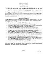
Page 4: ...e 6 Joystick panel explanation Page 2 4 Battery replacement Page 6 Lights flashing what do they mean Page 10 Jack operation Page 7 7a Locking the Joystick 80 amp Controller Page 2 Track adjustment Page 7 7a Safety Tips Page 1 Unlocking the drive pins Page 9 Speed selection Page 2 4 Stalling or Power out problem Page 11 Stalling or Power out problem Page 11 Lights flashing Page 10 Track adjustment ...

Page 5: ...ries Do not charge the batteries if the battery charger is wet Do not drive the IRV2000 in vehicle areas It is not a legal street vehicle It is not recommended to drive parallel on an incline greater than 15 degrees Do not drive up a slop of more than 20 degrees BACK THE MACHINE UP A STEEP GRADE going forward may cause it to go over backwards Do not ride the IRV2000 on a ramp that is not rated for...

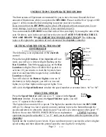
Page 6: ...ctivate If you want to re lock the Joystick have power on and touch the magnetic key on the Key Location red light You will also see the Battery Lights come on If the battery is fully charged you will see two red lights two yellow lights and two green lights You will see in the Speed Indicator window the speed number or actuator letter A or b SELECTING SPEEDS Press the Speed Selector until you see...

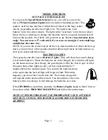
Page 7: ...ross small logs and ditches the same way NOTE If you run the center wheels all the way down and the caster all the way down you now have a three point setup that allows tight turns on hard surfaces as well as on carpet and throw rugs BATTERY LIGHTS The Joystick controller has six battery lights They will show how much charge is left in the batteries When the batteries are fully charged all six lig...

Page 8: ...ease speed and to the left to decrease speed To operate in that speed simply move the Lever forward or back You can also change speed while moving by pressing the Speed Mode Selector button The Joystick has a total of five speeds NOTE beginning operation in speed 1 or 2 lights is advisable until you are familiar with the operation of the Joystick DRIVING THE IRV 2000 WITH THE JOYSTICK Moving the J...

Page 9: ...t turns on hard surfaces as well as on carpet and throw rugs BATTERY LIGHTS The Joystick controller has ten Battery Lights They will show how much charge is left in the batteries When the batteries are fully charged all ten lights will light As the batteries loose their charge the green lights will be the first to quit If all of the green and yellow lights go out you have approximately 15 minutes ...

Page 10: ... safety In common with other electronic equipment correct handling and operation of the unit will ensure maximum reliability Please read this chapter carefully it will help you to keep your wheelchair reliable and safe 2 General An R net control system comprises a minimum of two modules Joystick Module and Power Module Because of the modular design the depth of the control system can be greatly in...

Page 11: ...ct the Communication Cables Holding the connector housing firmly push the connector into its mate until you can no longer see the yellow plastic The connectors are secured using a friction system To disconnect the Communication Cables Holding the connector housing firmly pull the connectors apart Do not hold or pull on the cable Always grip the connector when connecting and disconnecting When the ...

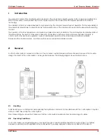
Page 12: ...ontrol system has two versions of Joystick Module with and without lighting control Most of the controls are common to both however the lighting buttons are only included on Joystick Module with lighting control Each of the controls is explained within this section SK77981 4 15 ...

Page 13: ...ns 4 2 1 On off Button The on off button applies power to the control system electronics which in turn supply power to the wheelchair s motors Do not use the on off button to stop the wheelchair unless there is an emergency If you do you may shorten the life of the wheelchair drive components 4 2 1 Horn Button The Horn will sound while this button is depressed 4 2 2 Speed Decrease Button This butt...

Page 14: ...for details 4 2 6 Hazard Warning Button and LED This button activates and de activates the wheelchairs hazard lights Depress the button to turn the hazards on and depress the button again to turn them off When activated the hazard LED and the indicator LED s will flash in sync with the wheelchair s indicators 4 2 7 Lights Button and LED This button activates and de activates the wheelchairs lights...

Page 15: ...creen is backlit Refer to section 5 for details on screen symbols 4 5 Charger Socket This socket should only be used for charging or locking the wheelchair Do not connect any type of programming cable into this socket Refer to section 10 for more details on charging This socket should not be used as a power supply for any other electrical device Connection of other electrical devices may damage th...

Page 16: ... current speed setting The speed setting is adjusted using the Speed Buttons 5 1 3 Current Profile The Profile Number describes which Profile the control system is currently operating in The Profile Text is the name or description of the Profile the control system is currently operating in 5 1 4 In Focus When the control system contains more than one method of direct control such as a secondary Jo...

Page 17: ... displayed when the control system has intentionally reduced its own power in order to protect itself against heat damage 5 1 11 Timer This symbol is displayed when the control system is changing between different states An example would be entering into Programming Mode The symbol is animated to show the sands falling 5 1 12 E Stop If the control system is programmed for latched drive or actuator...

Page 18: ...lchair s electrical system If the error is in a non active module for example in the ISM but with a drive Profile is selected then drive will still be possible however the diagnostic screen will appear intermittently 5 3 1 Identified Module This identifies which module of the control system has registered the problem PM Power Module JSM Joystick Module ISM Intelligent Seating lighting Module 5 3 2...

Page 19: ...s are good try charging the battery 5 4 Locking the Control System The Control System can be locked in one of two ways Either using a button sequence on the keypad or with a physical Key How the Control System is locked depends on how the wheelchair manufacturer has programmed the system 5 4 1 Keypad Locking To lock the wheelchair using the keypad While the control system is switched on depress an...

Page 20: ...elchair is now locked The following screen will be displayed To unlock the wheelchair If the control system has switched off press the On off button Insert and remove a PGDT supplied key into the Charger Socket The wheelchair is now unlocked 5 5 Actuator Selection Screen To adjust the seat position the actuator screen must be visible Depress the Mode Button to scroll through the Mode screens until...

Page 21: ...creen is reached or in the case of tan LED joystick module until the Speed Indicator returns to its normal state 6 LCD Screen Color This section covers those Joystick Modules that are fitted with a color LCD screen The color LCD screen is split into 3 areas of information The Top Bar the Base Bar and the Main Screen Area Each area is covered separately within this section ...

Page 22: ...l system on the screen will flash the joystick displaced screen You must release and center the joystick to resume normal operation If you do not release the joystick within five seconds the wheelchair will not be able to move even if you release the joystick and push it again The screen will display the diagnostic screen at this time You can reset this condition by switching the control system of...

Page 23: ...d One popular technique is to simply point the joystick in the direction you want to go The wheelchair will home in on the direction you push the joystick The further you push the joystick away from the rest position the faster the wheelchair will go Releasing the joystick will stop the wheelchair The intelligent speed control system minimizes the effects of slopes and different types of terrain T...

Page 24: ... wheelchair is in motion PGDT accept no liability for losses of any kind arising from the unexpected stopping of the wheelchair or arising from the improper use of the wheelchair or control system Do not operate the control system if the chair behaves erratically or shows abnormal signs of heating sparks or smoke Turn the control system off at once and consult your service agent PGDT accepts no li...

Page 25: ...screen remains on after initialization and that the battery gauge is displaying a reasonable amount of charge Push the joystick slowly forwards until you hear the parking brakes operate The chair may start to move Immediately release the joystick You must be able to hear each parking brake operate within a few seconds Repeat the test a further three times pushing the joystick slowly backwards left...

Page 26: ...elchair All wheelchair batteries will gradually lose their capacity as they age The most important factor that reduces the life of your batteries is the amount of charge you take from the batteries before you recharge them Battery life is also reduced by the number of times you charge and discharge the batteries To make your batteries last longer do not allow them to become completely flat Always ...

Page 27: ...ny kind arising from failure to comply with this condition Ensure that the charger plug pins are of the correct polarity to be compatible with the pin polarity shown on the control system s specific data sheet Failure to observe this condition could result in a burn hazard or fire hazard PGDT accepts no liability for losses of any kind arising from failure to comply with this condition Do not disc...

Page 28: ...rrect programming could result in an unsafe set up of a wheelchair for a user PGDT accepts no liability for losses of any kind if the programming of the control system is altered from factory pre set values 14 Joystick Knobs The knob fitted to your joystick is suitable for most applications If you would prefer another type there is a range of alternatives available Please contact your wheelchair d...

Page 29: ... in the IRV 2000 in the case of a roll over Acid fill batteries are not safe to charge in a house Gel cell deep cycle batteries will give you the best performance You may buy your batteries from Trac About Inc or from a good battery dealer Unplug the cord from the Joystick Remove the battery cover Remove the wing nuts on the terminal posts from the front battery Make sure you remember which wires ...

Page 30: ...f the machine rises about 1 inch off the ground Lift the foot rest Using the supplied multi wrench find the end marked 7 8 Turn the adjuster bolt on each side of the front frame counter clockwise until the adjuster bolts are loosened about 2 Using the end marked 3 4 loosen the two clamp bolts on each side of the frame top Push both front wheels back near the end of their slots Pull out the drive p...

Page 31: ...the foot rest Using the supplied multi wrench find the end marked 7 8 Turn the adjuster bolt on each side of the front frame counter clockwise until the adjuster bolts are loosened about 2 Using the end marked 3 4 loosen the two clamp bolts on each side of the frame top Push both front wheels back near the end of their slots Pull out the drive pin in the rear wheel and turn it 1 4 turn so that the...

Page 32: ...cross at an angle Cross small logs and ditches the same way NOTE If your run the center wheels all the way down and the caster all the way down you now have a three point setup that allows tight turns on hard surfaces as well on carpet The top illustration shows the center wheel and the tail wheel down This mode works best on hard surface and it is imperative on carpet The middle illustration show...

Page 33: ...ld now be in place Drive Pin REPLACING THE DRIVE PINS Upon occasion a drive pin may fail It is important that the new drive pin is reinstalled properly Remove the old pin by loosening the lock nut turn it counter clockwise Turn the drive pin out Turn the lock nut onto the new drive pin until most of the threads show Pull the plunger out and turn 1 4 turn Screw the drive pin into the drive arm unti...

Page 34: ... it back on Motor current has exceeded the limit due to overload Reduce load by reversing direction or check for blockage of the wheels or track Motors could be faulty Check motors by raising machine with jack instructions on earlier pages and blocking the machine up Run motors They should turn freely NOTE It is important you count the flashes before you call the Service Center Or call 1 800 458 8...

Page 35: ...y caused by a poor battery connection Check the battery and controller connections NOTE It is important you count the flashes before you call the Service Center Or call 1 800 458 8616 STALLING OUT OR POWER OUT If the IRV2000 should stall while driving off road the reason could possibly be that sand snow mud or some other obstruction is between the wheels and the track Stalling could also result fr...

Page 36: ...lts for tightness See the section for track adjustment REPLACING WHEEL BEARINGS First of all only people that know what they are doing should replace bearings Occasionally the wheel bearing will wear to the point they need replaced The bearings supplied in the wheels of the IRV 2000 are as good as we can find Nevertheless they will still wear out over a period of use Read the section TRACK REPLACE...

Page 37: ...e the gearbox block the machine up off the tracks remove the track remove the rear drive wheel remove the four bolts that hold the gearbox to the gearbox mount on the frame This information is for a service center only CLEANING AND WASHING When washing the IRV2000 be very careful not to spray high pressure water into the back of the machine Under the cover that the seat sets on is all of the elect...

Page 38: ...ield modifications not expressly furnished and authorized in writing by the engineering department of Trac About Inc Any unauthorized modifications immediately render this warranty null and void Trac About Inc will not be liable for any consequential damages nor for commercial consequential damages resulting from any breach of this warranty or any other warranty all of which are expressly disclaim...

Page 39: ...r TV stations and try to avoid coming close to them o If unintended movement or brake release occurs turn the powered wheelchair OFF as soon as it is safe o Be aware that adding accessories or components or modifying the powered wheelchair may make it more susceptible to interference from radio wave sources Note there is no easy way to evaluate their effect on the overall immunity of the powered w...

Page 40: ...PARTS LOCATION FOR THE TRAC ABOUT INC IRV2000 10 13 20 17 16 15 14 19 12 113 14a 21 115 112 103 100 108 22 23 111 11 18 25 120 116 108 114 119 101 118 24 26 110 110 119 102 117 ...

Page 41: ...r latch pin only 23 T7340 2 LATCH BATTERY COVER 24 TS2230 1 LEFT FRONT AXLE BRACKET 25 TS2220 1 RIGHT FRONT AXLE BRACKET 26 T2300 2 TRACK ADJUSTER BOLT 100 T7010 1 JOYSTICK CONTROL 101 T7020 1 POWER MODULE 102 T7030 1 ACTUATOR MODULE 103 T7040 2 MOTOR DRIVE 108 T7062 1 ACTUATOR REAR 108 T7060 1 ACTUATOR SIDE 110 T7070 2 BATTERY GROUP 24 12 VOLT 110 T7071 2 BATTERY GROUP 27 12 VOLT 100 amp hr 111 T...

Page 42: ... percent Range Approx 5 to 12 miles depending on terrain weight of driver and battery condition Standard Equipment Joystick Control with battery charge level lights and horn 24 Volt Battery Charger 2 12 Volt AGM Group 24 Batteries not included 2 4 Wide Track Belts instead of wheels Rear wheel drive with disengaging latch pins Track positioning for flat track three point and half track Tools for tr...

Page 43: ... against adverse conditions The circuit breaker can be manually disconnected by pressing in on the red button as shown Even though there is power at the batteries there is no power going through the system This picture shows the circuit breaker disconnected Notice the small black lever on an angle By rotating the lever up and away the circuit breaker is now reconnected and power is going through t...

Page 44: ...move the front battery Finished view THE FOLLOWING IMAGES AND INSTRUCTIONS ARE FOR REPLACING BATTERIES ON AN IRV2000 WITH THE ELEVATING SEAT SYSTEM THE IMAGES DEPECT A REHAB SEAT WHICH MAY OR MAY NOT BE THE SAME AS WHAT YOU HAVE THE CUSTOMER OR SERVICING ENTITY IS RESPONSIBLE FOR ALL CONNECTIONS AND OR FAILURES DUE TO IMPROPER INSTALLATION IN OTHER WORDS IF YOU DO NOT KNOW WHAT YOU ARE DOING FIND ...

Page 45: ...e seating apparatus forward making sure no wires are pulled too tight Disconnect remaining battery terminal leads and carefully remove the rear battery as shown Batteries successfully removed Simply reverse the order to install ...

Reviews: