background image

3

PREPARATION 

Plan Speed Control Placement

Mount Speed Control in V ehicle

1) 

2) 

For best choice we recommand you to use screws to mount the ESC to the chassis.

Use a small piece of double-sided tape on the ON/OFF switch. 

LED Indicator

Choose a location for the speed control that  is protected from road debris. To prevent radio 
interference, place the ESC far away from the radio receiver and keep the power wires as 
short as possible. Select a location that has good airflow ventilating. If the ESC gets air flow, 
it will run cooler; and that means it will be more efficient.

Soldering

Cut  the  ESC's  BLUE,  YELLOW  &  ORANGE  silicone  motor  power  wires  to  the  desired 

length and strip about 3.2mm-6.35mm  (1/8”-1/4”) of insulation from the end of each wire. 

“Pre-tin”the wire by heating the end and applying solder until it is thoroughly covered.

CAUTION: By very careful not to splash yourself with hot solder.

Place the ESC's BLUE Phase ‘A’ motor wire onto motor's ‘A’ solder tab and solder. Use 

soldering  iron to apply heat to exposed wire; begin adding solder to tip of soldering  iron 

and  wire. Add  just  enough  solder  to  form  a  clean  and  continuous  joint  from  the  plated 

area of the solder tab up onto the wire. Solder the ESC's YELLOW Phase‘B’ motor wire 

to  the  motor's  ‘B'  solder  tab  and  Solder  the  ESC's  ORANGE  Phase  ‘C'  motor  wire  to 

motor’s ‘C’ solder tab.

3) 

For  a  brushless  non-sensor  system,  there  is  no  polarity  on  the  motor  side  of  the 

controller.  Simply  solder  the  three  wires  to  your  motor.  If  the  car  runs  backwards  with 

forward throttle, simply swap any two of the motor wires and it will reverse the direction 

of the car.

Summary of Contents for 1/5 Brushless Sensorless Car ESC

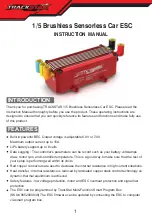
Page 1: ...controller s parameters can be record such as your battery volts amps draw motor rpm and controller temperature This is a good way to make sure that the rest of your setup is performing well within it...

Page 2: ...verheating To avoid signal interference please always turn on the transmitter first THEN turn on the ESC Do the opposite sequence when powering off Never use faulty accessories a broken motor may dama...

Page 3: ...f insulation from the end of each wire Pre tin the wire by heating the end and applying solder until it is thoroughly covered CAUTION By very careful not to splash yourself with hot solder Place the E...

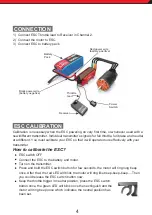
Page 4: ...beep once After that the red LED will blink the motor will ring like beep beep beep Then you could release the ESC switch button now Keep the throttle trigger in neutral position press the ESC switch...

Page 5: ...SC will be shut down Note 1 After running at full load the ESC will be very hot Note 2 When the motor is running the ESC can t be poweredoff by pressing the switch when the motor stops working the ESC...

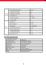
Page 6: ...Rate 2nd Stage Punch Rate TH Input Curve Throttle Dead Band Throttle Status Section General Setting Throttle Control Forward Brake Normal 25 100 in 1 increment 9 6 42V in 0 1V increment 85 185 1 99 i...

Page 7: ...pes to save Data Saving Time increment Single Start storage once entering in main program Cycle Press control storage entering in main program 0 1S 10S Voltage Current Throttle Current RPM ESC Tempera...

Page 8: ...hm 4 8S LiPo 6 0V 7 4V 15A 111x44x37mm LxWxH 359g without wire KV 1100 4 Poles Punch Rate Switch Point 1st Stage Punch Rate 2nd Stage Punch Rate TH Input Curve Throttle Dead Band Throttle Status Drag...

Page 9: ...g or solder tabs to short circuit or any damage caused by a crash flooding or natural disaster Because TRACKSTAR has no control over the connection use of the speed control or other related electronic...

Page 10: ...NOTES 10...

Reviews: