GB
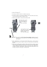
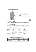
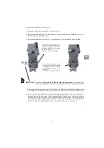
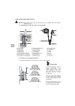
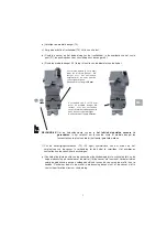
b) Remove the mobile half-clamp (13).
c) Make sure the pull wire rope (16) is free of any load.
d) Position the load limiter on the idle strand on the wire rope near the fixed point (21), with
the cable gland pointing upward.
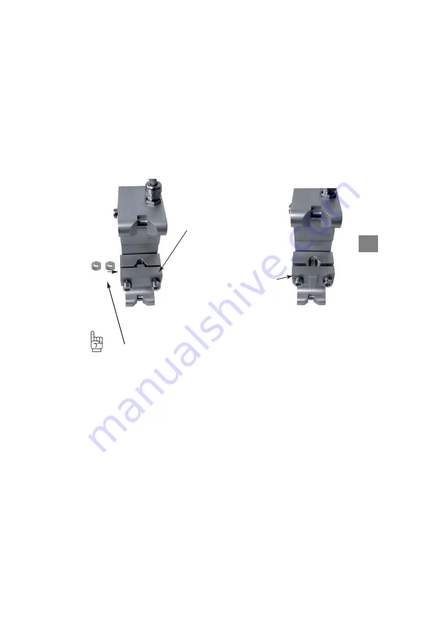
e) Reinstall the mobile half-clamp (13) in accordance with the diameter of the wire rope.
IMPORTANT:
To ensure the repeatability of
the factory preset sensors
, you must reinstall
the spacers supplied with the device between the fixed and mobile half-clamps.
f) Evenly adjust the mounting screws (12) (0.5 kgm) to avoid any risk of the load limiter moving
with respect to the wire rope. Too much clamping force can result in damage to the clamp.
g) Check that the load limiter is correctly positioned by performing a lifting movement up to
the high limit switch and check that the pulley block (18) does not touch the load limiter.
If necessary, correct the limit switch adjustment to keep sufficient clearance between
the load limiter and the pulley block. Also check, when the pulley block is at the high limit
switch, that the load limiter does not come into contact with the crane structure.
For the small wire ropes (5 to
8 mm), the mobile half-clamp
ensuring clamping must be
positioned with the nose pointing
toward the sensor.
Clamping screw length:
30 mm
.
For 9 to 16 mm wire ropes,
the mobile half-clamp ensuring
clamping must be positioned
with the flat part pointing toward
the sensor.
Clamping screw length:
35 mm
.
7

