10
GB
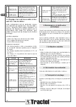
ACTIONS
REMARKS
1
Lift the two loads
(100% + 10% WLL)
by about 10 cm.
The additional 10% represents
the overshoot value authorized
in accordance with the European
directives.
2
Adjust the safety
threshold S1.
Gradually screw in the threshold
adjustment screws (rep 3) until
the NC contact opens (§4.4).
Use a multimeter, for example, to
check the state of the contact.
3
Check correct
operation.
It must be possible to lift the
“WLL” load.
It must not be possible to lift the
“WLL” load + 10%.
Depending on the lifting speed,
the dynamic effect may produce
an unintentional overload. In this
case, consult with a technician
capable of integrating a signal
filtering device (example: time-
out, etc.).
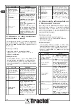
5.3.
Adjustment of a safety threshold and
an intermediate threshold
This configuration satisfies a number of applications
such as, for example, fast lifting speed conditioned to
load lifted. Audible or visual signal triggered at 90% of
the WLL. etc.
Preliminary conditions:
–
Load limiter correctly mounted and wired.
–
Adjustment screws unscrewed to the maximum.
–
Hook free of any load.
Equipment required:
–
A load (called «WLL») equivalent to 100% of the
nominal capacity authorized for the lifting machine.
–
An additional load equivalent to 10% of the «WLL».
–
A load «X» equivalent to the value of the intermediate
threshold.
ACTIONS
REMARKS
1
Lift the two loads
(100% + 10% WLL)
by about 10 cm.
The additional 10% represents
the overshoot value authorized
in accordance with the European
directives.
2
Adjust the safety
threshold S1.
Gradually screw in the threshold
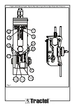
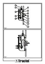
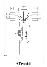
adjustment screws (rep 3) until
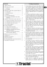
the NC contact opens (§4.4).
Use a multimeter, for example, to
check the state of the contact.
3
Check correct
operation.
It must be possible to lift the
«WLL» load.
It must not be possible to lift the
«WLL» load + 10%.
Depending on the lifting speed,
the dynamic effect may produce
an unintentional overload. In this
case, consult with a technician
capable of integrating a signal
filtering device (example: time-
out, etc.).
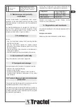
4
Lift the intermediate
load “X”.
Wait for the load to stabilize
before adjusting the threshold.
5
Adjust the
intermediate
threshold S2.
Gradually screw in the threshold
adjustment screws (rep 3) until
the NC contact opens (§4.4).
Use an ohmmeter, for example,
to check the state of the contact.
6
Check correct
operation.
Check that micro switch S2
opens when the load “X” is lifted.
5.4.
Adjustment of a safety threshold and
a “Wire rope slack” threshold
This configuration is particularly designed to detect a
“Wire rope slack” situation or “presence of a minimum
load” below which the signal generated by the micro
switch will be processed, for example, to stop the down
movement of the lifting hook.
Preliminary conditions:
–
Load limiter correctly mounted and wired.
–
Adjustment screws unscrewed to the maximum.
–
Hook free of any load.
Equipment required:
–
A load (called “WLL”) equivalent to 100% of the
nominal capacity authorized for the lifting machine.
–
An additional load equivalent to 10% of the “WLL”.
–
A load “X” equivalent to the value of the “Wire rope
slack” threshold.
ACTIONS
REMARKS
1
Lift the two loads
(100% + 10% WLL)
by about 10 cm.
The additional 10% represents
the overshoot value authorized
in accordance with the European
directives.
2
Adjust the safety
threshold S1.
Gradually screw in the threshold
adjustment screws (rep 3) until
the NC contact opens (§4.4).
Use a multimeter, for example, to
check the state of the contact.
3
Check correct
operation.
It must be possible to lift the
“WLL” load.
It must be possible to lift the
“WLL” load + 10%.
Depending on the lifting speed,
the dynamic effect may produce
an unintentional overload. In this
case, consult with a technician
capable of integrating a signal
filtering device (example: time-
out, etc.).
4
Lift the intermediate
load “X”
Wait for the load to stabilize
before adjusting the threshold.
5
Adjust the safety
threshold S2.
Gradually screw in the threshold
adjustment screws (rep 3) until
the NO contact opens (§4.4).
For more accuracy, take into
account the hysteresis in the
setting.
Use a multimeter, for example, to
check the state of the contact.
Summary of Contents for dynasafe Mecha 3.2
Page 3: ...3 1 5 4 2 3 6 7 8 9 10 11 12 13 Fig 2 Fig 3 ...
Page 4: ...4 Fig 4 ...
Page 52: ...52 ...
Page 53: ...53 ...
Page 54: ...54 ...
Page 55: ......


