background image

6

GB

delivered into a state of commissioning (or connection 

to other elements for commissioning).

“Supervisor”

:  Individual  or  party  responsible  for  the 

management and safe use of the product described in 

the manual.

“Technician”:

  Qualified  person  familiar  with  the 

product,  in  charge  of  the  maintenance  operations 

described and permitted in the manual.

“Operator”

: Individual using the product in accordance 

with the instructions in this manual

2.2. Pictograms

 “DANGER”:

  When  placed  at  the  beginning  of 

a  paragraph,  it  indicates  instructions  for  preventing 

injuries  ranging  from  minor  to  fatal  and  also 

environmental damage.

 “IMPORTANT”:

  When  placed  at  the  beginning 

of a paragraph, it indicates instructions for preventing 

product  failure  or  damage  which  would  not  directly 

endanger  the  life  or  health  of  operators  or  other 

individuals and/or which may harm the environment.

 “NB”:

  When  placed  at  the  beginning  of  a 

paragraph,  it  indicates  the  necessary  precautions  to 

apply for efficient and ergonomic installation, use and 

maintenance.

:

 When placed on the product itself or a product 

component, it indicates the need to read the operating 

and maintenance manual.

authorisation,  especially  as  concerns  replacement 

of  genuine  spare  parts  by  parts  from  another 

source.

12. 

For  definitive  removal  from  service  of  the  device, 

the  device  must  be  scrapped  under  conditions 

preventing  re-use  of  the  device.  All  environment 

protection regulations must be observed.

13. 

Before  using  this  device  with  complementary 

equipment  relaying  its  signals  on  an  operating 

system, the user or installer must first ensure that 

an analysis has been carried out to determine the 

specific risks involved in the operating configuration 

implemented, and all appropriate safety measures 

must be taken accordingly.

14. 

The  load  limiter  covered  by  the  manual  satisfies 

the requirements of the European regulations and 

must be verified for compliance with the regulations 

of any other country in which it may be used, prior 

to  commissioning  and  use.  All  applicable  safety 

regulations must be observed.

2. 

Definitions and pictograms

2.1. 

Definitions

In  this  manual,  the  following  terms  are  defined  as 

follows:

“Product”

: Item or equipment described in this manual 

and delivered complete in the standard version, or in its 

various existing models.

“Installation”

:  All  the  operations  required  to  bring 

the  complete  product  from  the  state  in  which  it  was 

3. 

Description of load limiter dynasafe

TM 

Mecha 3.2

3.1. Presentation

The load limiter dynasafe

TM

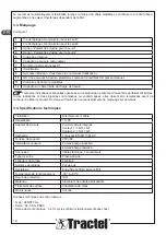
 Mecha 3.2 is a mechanical load limiter for wire ropes operating on the principle of a 

potential-free contact which is tripped when the tension in the wire rope exceeds the preset limit.

This  load  limiter  is  specially  designed  to  manage  one  or  two  safety  thresholds  on  small  and  medium  capacity 

overhead travelling cranes.

3.2. Operating principle

The operating principle of dynasafe

TM 

Mecha 3.2 is based on the deformation of the load limiter body through a 

tangential force, which is proportional to the force exerted on the wire rope when pulled.

When the deformation of the load limiter body is above a limit, the integrated micro-switch opens.

The contact is automatically reset once the tension in the wire rope is below the set limit increased by a hysteresis 

value depending of the effort.

Summary of Contents for dynasafe Mecha 3.2

Page 1: ...nasafe Mecha 3 2 Installation operating and maintenance manual English Original manual GB Manuel d installation utilisation et maintenance Français Traduction de la notice originale FR Installations Gebrauchs und Wartungsanleitung Deutsch Übersetzung der Originalanleitung DE Handleiding voor installatie gebruik en onderhoud Nederlands Vertaling van de oorspronkelijke handleiding NL Manual de insta...

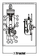
Page 2: ...2 7 10 9 11 12 5 6 8 2 4 1 3 Figure Abbildung Figuur Figura Φιγούρα Figur Kuva Figur Rysunek Рисунок Fig 1 ...

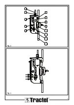
Page 3: ...3 1 5 4 2 3 6 7 8 9 10 11 12 13 Fig 2 Fig 3 ...

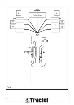
Page 4: ...4 Fig 4 ...

Page 5: ...this manual Never use the load limiter for a load exceeding the working load limit indicated on the device In its standard version the load limiter must never be used in an explosive atmosphere 8 The load limiter must not be used in a man lifting line without first checking the utilisation factors required to ensure the safety of persons and more generally the applicable safety regulations for the...

Page 6: ... user or installer must first ensure that an analysis has been carried out to determine the specific risks involved in the operating configuration implemented and all appropriate safety measures must be taken accordingly 14 The load limiter covered by the manual satisfies the requirements of the European regulations and must be verified for compliance with the regulations of any other country in w...

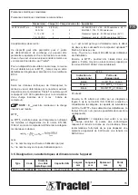
Page 7: ...ced before continuing to use the product Tractel can supply new marking materials on request 3 4 Technical specifications Installation Directly on idle strand Repeatability 1 FS Measurement sensor 2 integrated micro switches Contact 1 1 NO 1 NC Contact 2 1 NO 1 NC Category 1 as EN ISO 13849 1 Cut out voltage 250 VAC Cut out intensity 2A max inductive load 4A max resistive load Connection Electrica...

Page 8: ...me of use between the start of two successive cycles of the component dynasafeTM Mecha 3 2 in this case dop hop and tcycle have to be defined by the installation user Then the MTTFD could be classified in a range Low medium or high as proposed by EN ISO 13849 1 in table 4 MTTFD Denotation of each channel Range of each channel Low 3 years MTTFD 10 years Medium 10 years MTTFD 30 years High 30 years ...

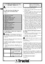
Page 9: ... 3 Load limiter electrical connection a Correctly secure the electrical cable of the load limiter up to the control cabinet Installation b Connectthecontrolcircuitcontactwiresasinstructed in 4 4 Micro switch interrupting capacity 4 A 250 VAC Reset hysteresis depending on the effort between 50 and 200 kg Safety feature should be managed by one of the NC contacts of the load limiter in this way an o...

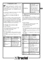
Page 10: ...a signal filtering device example time out etc 4 Lift the intermediate load X Wait for the load to stabilize before adjusting the threshold 5 Adjust the intermediate threshold S2 Gradually screw in the threshold adjustment screws rep 3 until the NC contact opens 4 4 Use an ohmmeter for example to check the state of the contact 6 Check correct operation Check that micro switch S2 opens when the loa...

Page 11: ... 8 Declaration of conformity Copy of declaration conformity in appendix 9 Transport and storage During storage and or transport the product must be Packed in its original packaging Stored in a dry location Stored at a temperature between 30 C and 80 C Protected from chemical mechanical or any other type of attack 10 Product disposal and environmental protection The product must be disposed of in a...

Page 12: ...ts sont constatés 6 Prenez toutes les mesures nécessaires pour éviter tout choc ou impact sur votre limiteur de charge 7 Le limiteur de charge ne doit jamais être utilisé à d autres fins que celles décrites dans le présent manuel N utilisez jamais le limiteur de charge pour une charge dépassant la limite de charge de travail indiquée sur l appareil Dans sa version standard le limiteur de charge ne...

Page 13: ... l autorisation de Tractel notamment en ce qui concerne le remplacement de pièces détachées d origine par des pièces provenant d une autre source 12 Pour la mise hors service définitive de l appareil celui ci doit être mis au rebut dans des conditions empêchant sa réutilisation Toutes les réglementations relatives à la protection de l environnement doivent être respectées 13 Avant d utiliser ce di...

Page 14: ...t être parfaitement lisibles Si des indications et des étiquettes sont enlevées ou endommagées elles doivent être remplacées avant de continuer à utiliser le produit Tractel peut fournir de nouveaux éléments de marquage sur demande 3 4 Spécifications techniques Installation Directement sur câble Répétabilité 1 PE Capteur de mesure 2 microrupteurs intégrés Contact 1 1 NO 1 NF Contact 2 1 NO 1 NF Ca...

Page 15: ... norme EN ISO 13849 1 en tenant compte de la B10d et de la catégorie mentionnées ci dessus où avec dop le nombre moyen d heures d utilisation par jour hop le nombre moyen de jours d utilisation par an tcycle est le temps moyen d utilisation entre le début de deux cycles successifs du composant dynasafeTM Mecha 3 2 dans ce cas Le dop l hop et le tcycle doivent être définis par l utilisateur de l in...

Page 16: ...haut e Fermez le demi collier mobile 8 sur le câble d acier f Réglez uniformément les vis de montage 9 9 Nm pour éviter tout risque de déplacement du limiteur de charge par rapport au câble métallique Une force de serrage trop importante peut endommager le collier g Vérifiez que le limiteur de charge est correctement positionné en effectuant un mouvement de levage jusqu à l interrupteur de fin de ...

Page 17: ...ever la charge CMU Il ne doit pas être possible de soulever la charge CMU 10 En fonction de la vitesse de levage l effet dynamique peut produire une surcharge involontaire Dans ce cas consultez un technicien capable d intégrer un dispositif de filtrage du signal exemple temporisation etc 5 3 Réglage d un seuil de sécurité et d un seuil intermédiaire Cette configuration permet de satisfaire un cert...

Page 18: ...rcharge involontaire Dans ce cas consultez un technicien capable d intégrer un dispositif de filtrage du signal exemple temporisation etc 4 Levage la charge intermédiaire X Attendez que la charge se stabilise avant de régler le seuil 5 Régler le seuil de sécurité S2 Visser progressivement les vis de réglage du seuil rep 3 jusqu à ce que le contact NO s ouvre 4 4 Pour plus de précision tenez compte...

Page 19: ...atériaux doivent être recyclés par des organismes spécialisés Au moment de l élimination seules des personnes formées peuvent démonter le produit pour en séparer les composants Composant À traiter comme un déchet du type Corps du produit Aluminium et acier Microrupteurs Matériel électronique Tractel peut recycler le produit Veuillez contacter Tractel pour plus d informations 11 Règlements et norme...

Page 20: ...ustand ist Bei Funktionsstörungen muss der Hubkraftbegrenzer zur Überprüfung an den Hersteller eingeschickt werden 6 Schützen Sie den Hubkraftbegrenzer vor Stößen aller Art 7 Der Hubkraftbegrenzer darf nie für andere als die in dieser Anleitung beschriebenen Arbeiten verwendet werden Er darf nie für Lasten benutzt werden die die auf dem Gerät angegebene Tragfähigkeit übersteigen In der Standardaus...

Page 21: ...von von Tractel genehmigter Ausbau oder Instandsetzungsarbeiten ab insbesondere beim Ersatz von Originalteilen durch Teile anderer Herkunft 12 Bei einer endgültigen Außerbetriebnahme muss das Gerät so ausgemustert werden dass seine Benutzung unmöglich ist Geltende Umweltschutzvorschriften sind zu beachten 13 JedeBenutzungdesGerätsmitZusatzausrüstungen die Signale an ein Betriebssystem übertragen m...

Page 22: ...sen deutlich lesbar sein Entfernte oder beschädigte Hinweise und Etiketten müssen vor einer weiteren Nutzung des Geräts erneuert werden Neue Markierungen sind auf Anfrage bei Tractel erhältlich 3 4 Technische Daten Installation Direkt auf dem toten Seilstrang Wiederholbarkeit 1 v E Messgerät 2 integrierte Mikroschalter Kontakt 1 1 Schließer NO 1 Öffner NC Kontakt 2 1 Schließer NO 1 Öffner NC Kateg...

Page 23: ...ter Berücksichtigung des oben genannten B10D und der Kategorie bewertet werden wobei mit dop die durchschnittliche Anzahl der Betriebsstunden pro Tag hop die durchschnittliche Anzahl der Nutzungstage pro Jahr tcycle die durchschnittliche Nutzungszeit zwischen dem Start von zwei aufeinanderfolgenden Zyklen der Komponente dynasafeTM Mecha 3 2 in diesem Fall dop hop und tcycle müssen vom Installation...

Page 24: ...ren e Den beweglichen Bügel 8 am Seil schließen f Die Befestigungsschrauben 9 symmetrisch so einstellen 9 Nm dass jede Verschiebung des Hubkraftbegrenzers gegenüber dem Seil ausgeschlossen wird Ein übermäßiger Anzug kann die Klemme beschädigen g Die ordnungsgemäße Positionierung des Hubkraftbegrenzers prüfen indem die Hubbewegung bis zum oberen Endschalter durchgeführt wird und sicherstellen dass ...

Page 25: ...nd nach bis zum Öffnen des Öffners festziehen siehe Kapitel 4 4 Zum Beispiel ein Ohmmeter zur Prüfung des Zustands des Kontakts benutzen 3 Den einwandfreien Betrieb prüfen Es muss möglich sein die der Tragfähigkeit entsprechende Last zu heben Es muss unmöglich sein die der Tragfähigkeit 10 entsprechende Last zu heben Je nach Hubgeschwindigkeit ist es möglich dass der Anfahrschock eine ungewollte Ü...

Page 26: ...ntspricht Eine Last X die dem Wert der Schlaffseilschaltschwelle entspricht MASSNAHMEN ANMERKUNGEN 1 Die beiden Lasten 100 10 der Tragfähigkeit um ca 10 cm anheben Die zusätzlichen 10 entsprechen dem von den europäischen Richtlinien zugelassenen Überschreitungswert 2 Die Sicherheitsschaltschwelle S1 einstellen Die Schaltschwellen Stellschraube Mark 3 nach und nach bis zum Öffnen des Öffners festzi...

Page 27: ...ackt sein An einem trockenen Ort gelagert werden Bei Temperaturen zwischen 30 C und 80 C gelagert werden Vor chemischen mechanischen und anderen Belastungen geschützt werden 10 Entsorgung des Produkts und Umweltschutz Das Produkt muss in Übereinstimmung mit den einschlägigen Vorschriften im Land der Aufstellung entsorgt werden Die unterschiedlichen Produktbestandteile müssen gemäß der nachstehende...

Page 28: ...t Stuur de lastbegrenzer terug naar de fabrikant voor revisie indien u een defect waarneemt 6 Neem alle stappen die nodig zijn om schokken of impact op uw lastbegrenzer te voorkomen 7 De lastbegrenzer mag nooit worden gebruikt voor andere doeleinden dan die beschreven staan in deze handleiding Gebruik de lastbegrenzer nooit voor een belasting die de werklastlimiet zoals staat aangegeven op het toe...

Page 29: ...anpassingen aan het toestel of door het verwijderen van enige onderdelen van het toestel 11 Tractel is niet aansprakelijk voor zaken die voortkomen uit ontmantelingsactiviteiten of reparaties die worden uitgevoerd op het toestel zonder autorisatie van Tractel met name in het geval van vervanging van originele reserve onderdelen door onderdelen van een andere bron 12 Voor definitieve ontmanteling v...

Page 30: ...tel 8 Identificatie 9 Symbool dat U moet de gebruikershandleiding lezen aangeeft 10 QR code naar tracinfo met daarin CE certificaat huidige handleiding 11 Diameters van compatibele staalkabels 12 Capaciteit op draad werklastlimiet Alle door de fabrikant op het product aangebrachte aanduidingen en etiketten moeten volledig leesbaar blijven Als er aanwijzingen en labels zijn verwijderd of beschadigd...

Page 31: ...t schakelen van inductieve belasting van 2 A bijv magneetschakelaar OPMERKING B10d kan beter zijn als de inductieve belasting wordt verlaagd MTTFD MTTFD moet door de integrator worden geëvalueerd door middel van de formules en diagrammen van de norm EN ISO 13849 1 rekening houdend met de B10d en categorie zoals hierboven beschreven where met dop het gemiddelde aantal gebruiksuren per dag hop het g...

Page 32: ...eer de lastbegrenzer op de onbenutte draad op de staalkabel in de buurt van het vaste punt waarbij de kabelwartel 2 omhoog wijst e Sluit de mobiele halve klem 8 op de staalkabel f Pas de montageschroeven 9 9 Nm gelijkmatig aan Zo vermijdt u het risico op beweging van de lastbegrenzer met betrekking tot de staalkabel Te veel klemkracht kan resulteren in schade aan de klem g Controleer of de lastbeg...

Page 33: ...adingen 100 10 WLL ongeveer 10 cm De extra 10 geeft de overschrijdingswaarde weer zoals geautoriseerd in overeenstemming met de Europese richtlijnen 2 De veiligheidsdrempel S1 aanpassen Schroef de instelschroeven van de drempel rep 3 geleidelijk vast tot het NC contact opent 4 4 Gebruik bijvoorbeeld een multimeter om de staat van het contact te controleren 3 Controleer de juiste bediening Het moet...

Page 34: ...dingswaarde weer zoals geautoriseerd in overeenstemming met de Europese richtlijnen 2 De veiligheidsdrempel S1 aanpassen Schroef de instelschroeven van de drempel rep 3 geleidelijk vast tot het NC contact opent 4 4 Gebruik bijvoorbeeld een multimeter om de staat van het contact te controleren 3 Controleer de juiste bediening Het moet mogelijk zijn om de WLL lading te heffen Het moet mogelijk zijn ...

Page 35: ...tproductmoetwordenafgevoerdinovereenstemming met de regelgeving die van toepassing is in het land van gebruik De verschillende productonderdelen moeten worden gerecycled op basis van de onderstaande tabel nadat metalen en synthetische materialen zijn gescheiden Deze materialen moeten worden gerecycled door gespecialiseerde organisaties Op het moment van verwijdering mogen alleen getrainde personen...

Page 36: ...ecesarias para evitar golpes o impactos en el limitador de carga 7 El limitador de carga no debe utilizarse nunca para ningún otro propósito que no sea el descrito en este manual No utilice nunca el limitador para una carga que exceda el límite de carga de trabajo que se indica en el dispositivo En su versión estándar el limitador de carga no debe utilizarse nunca en una atmósfera explosiva 8 El l...

Page 37: ...ctel especialmente en lo que respecta a la sustitución de las de piezas de repuesto originales por piezas de otro proveedor 12 Para que el dispositivo se retire definitivamente del servicio este debe desecharse en condiciones que impidan su reutilización Deben respetarse todas las normas de protección medioambiental 13 Antes de utilizar este dispositivo con equipos complementarios que transmitan s...

Page 38: ... límite de carga de trabajo El texto de las indicaciones y etiquetas que figura en el producto del fabricante debe poder leerse sin dificultad Si se han extraído estas indicaciones o etiquetas o bien se encuentran dañadas deben sustituirse antes de continuar utilizando el producto Tractel puede suministrarle material de marcado nuevo previa solicitud 3 4 Especificaciones técnicas Instalación Direc...

Page 39: ...El MTTFD debe ser evaluado por el integrador utilizando las fórmulas y los diagramas de la norma EN ISO 13849 1 y teniendo en cuenta el B10d y la categoría mencionada anteriormente donde Con dop el número medio de horas de uso por día hop el número medio de días de uso por año tciclo es el tiempo medio de uso entre el inicio de dos ciclos sucesivos del componente dynasafeTM Mecha 3 2 en este caso ...

Page 40: ...8 del cable de acero f Ajuste uniformemente los tornillos de montaje 9 9 Nm para evitar cualquier riesgo de que el limitador de carga se mueva con respecto al cable de acero Demasiada fuerza de sujeción puede dañar la abrazadera g Compruebe que el limitador de carga esté colocado correctamente realizando un movimiento de elevación hasta el interruptor de fin de carrera alto y compruebe que el equi...

Page 41: ...tado del contacto 3 Compruebe que funciona correctamente Debe ser posible elevar la carga CTL No debe ser posible elevar la carga CTL 10 En función de la velocidad de elevación el efecto dinámico puede producir una sobrecarga involuntaria En este caso consulte con un técnico capaz de integrar un dispositivo de filtrado de señales por ejemplo tiempo agotado etc 5 3 Ajuste de un umbral de seguridad ...

Page 42: ...ar el estado del contacto 3 Compruebe que funciona correctamente Debe ser posible elevar la carga CTL Debe ser posible elevar la carga CTL 10 En función de la velocidad de elevación el efecto dinámico puede producir una sobrecarga involuntaria En este caso consulte con un técnico capaz de integrar un dispositivo de filtrado de señales por ejemplo tiempo agotado etc 4 Eleve la carga intermedia X Es...

Page 43: ...rentes componentes del producto deben reciclarse siguiendo la tabla que se muestra a continuación después de hacer una separación entre materiales metálicos y sintéticos Estos materiales deben ser reciclados por organismos especializados En el momento de desechar el producto solo los profesionales técnicos están capacitados para desmontar sus componentes Componente Tipo de residuo Cuerpo del produ...

Page 44: ...venire urti o impatti al limitatore di carico 7 Il limitatore di carico è destinato esclusivamente allo scopo descritto nel presente manuale Non utilizzare mai il limitatore di carico per carichi che superino il carico massimo di utilizzo indicato sul dispositivo Nella versione standard non usare mai il limitatore di carico in atmosfera esplosiva 8 Non usare il limitatore di carico in un sistema p...

Page 45: ...re che trasmette i suoi segnali a un sistema operativo l utente o l installatore deve prima assicurarsi che sia stata svolta un analisi per determinare i rischi specifici che la configurazione operativa implementata comporta e che tutte le misure di sicurezza appropriate siano state prese di conseguenza 14 Il limitatore di carico trattato nel manuale soddisfa i requisiti delle norme europee e prim...

Page 46: ...prodotto Su richiesta Tractel può fornire nuovi elementi di marcatura 3 4 Specifiche tecniche Installazione Direttamente su fune inattiva Ripetibilità 1 FS Sensore di misurazione 2 microinterruttori integrati Contatto 1 1 normalmente aperto 1 normalmente chiuso Contatto 2 1 normalmente aperto 1 normalmente chiuso Categoria 1 conforme a EN ISO 13849 1 Tensione di rilascio 250 V CA Intensità di rila...

Page 47: ...re di utilizzo al giorno dop numero medio di giorni di utilizzo all anno tcycle è il tempo medio di utilizzo tra l inizio di due cicli successivi del componente dynasafeTM Mecha 3 2 in questo caso dop hop e tcycle devono essere definiti dall utente dell installazione Successivamente l MTTFD può essere classificato in un intervallo basso medio o alto come proposto da EN ISO 13849 1 nella tabella 4 ...

Page 48: ...a di sollevamento non tocchi il limitatore di carico Se necessario correggere la regolazione dell interruttore di finecorsa per mantenere una distanza sufficiente tra il limitatore di carico e il bozzello Verificare inoltre che quando il bozzello si trova sull interruttore di finecorsa superiore il limitatore di carico non entri in contatto con la struttura della gru 4 3 Collegamento elettrico del...

Page 49: ...rettamente Viti di regolazione svitate al massimo Gancio senza carico Attrezzatura richiesta Un carico chiamato WLL Working Load Limit equivalente al 100 della capacità nominale autorizzata per la macchina di sollevamento Un carico aggiuntivo equivalente al 10 del WLL Un carico X equivalente al valore della soglia intermedia AZIONI COMMENTI 1 Sollevare i due carichi 100 10 WLL di circa 10 cm Il 10...

Page 50: ...mento corretto Verificare che il microinterruttore per la soglia S2 si attivi al raggiungimento della condizione di allentamento della fune 6 Manutenzione e ispezione periodica Tractel raccomanda di verificare periodicamente il funzionamento corretto del limitatore di carico e la precisione delle impostazioni della soglia in base alle norme applicabili Per questo tipo di dispositivo non è prevista...

Page 51: ...acciaio Microinterruttori Componenti elettronici Tractel può riciclare il prodotto Contattare Tractel per maggiori informazioni 11 Norme e standard Il prodotto descritto nel presente manuale è conforme ai seguenti standard Standard europei Direttiva macchine 2006 42 EC e ISO13849 1 ...

Page 52: ...52 ...

Page 53: ...53 ...

Page 54: ...54 ...

Page 55: ......

Page 56: ...is Laval France Phone 33 4 78 50 18 18 Fax 33 4 72 66 25 41 Email info tractelsolutions tractel com GREAT BRITAIN Tractel UK Limited Old Lane Halfway Sheffield S20 3GA United Kingdom Phone 44 114 248 22 66 Email sales uk tractel com ITALY Tractel Italiana SpA Viale Europa 50 Cologno Monzese Milano 20093 Italy Phone 39 02 254 47 86 Fax 39 02 254 71 39 Email infoit tractel com NETHERLANDS Tractel Be...

Reviews: