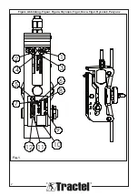
8
GB
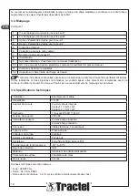
Voltage (max)
Load (A)
Inductive load (A)
Approval
V4NT7/V4NST7-UL
250 VAC
5 (0.75 pf)
UL1054/CSA 22.2 No. 55 - 6.000 operations - 65° C
250 VAC
5
2
EN61058-1, T85, 10.000 operations
0 - 15 VDC
5
3
General rating - 50.000 operations (85° C)
15 - 30 VDC
5
3
General rating - 50.000 operations (85° C)
Safety considerations:
This device can be set for 2 overload trigger points
which can be set separately. For a safety function each
of them is a single channel considered as a “well tried
component” by Tractel
®
.
For a safety device with single channel, PL level is
determined by MTTF
D
(mean time between dangerous
failure) emanating from B
10D
monitoring.
B10d:
According the technical data of the switch, the
life duration is determined by maximum switching
operations. Tractel
®
considers B is 10.000 operations
for switching inductive load of 2 A (eg: contactor coil).
NOTE:
B
10d
can be better if the inductive load
is reduced.
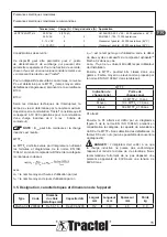
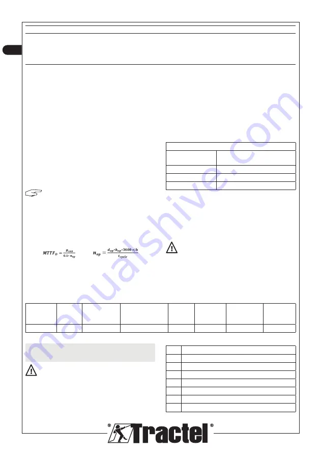
MTTF
D
:
MTTF
D
must be evaluated by the integrator using the
formulas and diagrams of the standard EN ISO 13849-1
considering the B10d and category mentioned above
where
with
d
op
= the average number of hours of use per day
h
op
= the average number of days of use per year
t
cycle
= is the average time of use between the start of
two successive cycles of the component dynasafe
TM
Mecha 3.2 in this case.
d
op
, h
op
and t
cycle
have to be defined by the installation
user.
Then, the MTTF
D
could be classified in a range: Low,
medium or high as proposed by EN ISO 13849-1 in
table 4
MTTF
D
Denotation of
each channel
Range of
each channel
Low
3 years ≤ MTTF
D
< 10 years
Medium
10 years ≤ MTTF
D
< 30 years
High
30 years ≤ MTTF
D
≤ 100 years
Achieved PL:
After that, achieved PL is issued out by a diagram (figure
5 in EN ISO 13849-1) taking in consideration category,
DC monitoring capability and MTTF
D
. Without failure
detection DC factor is ‘none’ (no diagnostic coverage
possibility).
DANGER:
The integrator must take care that
the inductive load could damage the device and
could reduce the electrical life duration. We strongly
recommend not to exceed an apparent power of 80VA
with 48VAC voltage max.
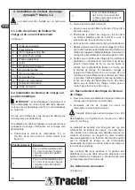
3.5.
Designation, characteristics and outline dimensions
Type
Code
Wire rope
diameter mm
Capacity daN
Width
mm
Length
mm
Thickness
mm
Weight
kg
Mecha 3.2
293599
From 5 to 16 From 200 to 3200
112
160
48
0.9
4.
Installation of load limiter dynasafe
TM
Mecha 3.2
Product must be installed by a qualified technician.
4.1.
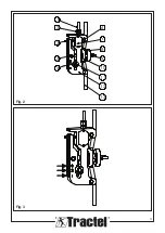
Parts list of load limiter and its
environment
See figure 2.
1
Connecting cable
2
Cable gland
3
Adjustment screw and nutlock
4
Assembling pin
5
Nameplate
6
Guide
7
Switch cover
8
Mobile half clamp
Summary of Contents for dynasafe Mecha 3.2
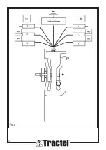
Page 3: ...3 1 5 4 2 3 6 7 8 9 10 11 12 13 Fig 2 Fig 3 ...
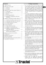
Page 4: ...4 Fig 4 ...
Page 52: ...52 ...
Page 53: ...53 ...
Page 54: ...54 ...
Page 55: ......


