4.3 THREE PIECE SKYBEAM ASSEMBLY. (MRB3P)
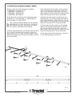
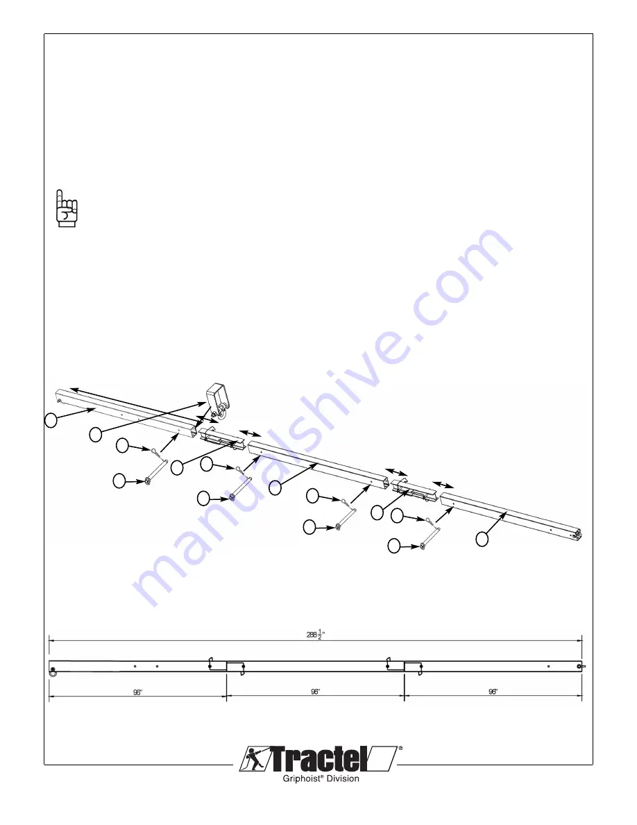
Ensure you have the correct components for assembly
2 – MRBL0200 Connection Beam (1)
1 – MRBL0210 4’ Front Beam (2)
1 – MRBL0220 4’ Middle Beam (3)
1 – MRBL0230 4’ Rear Beam (4)
Lie the components on the ground in the following sequence:
Front beam (2) – Connection Beam (1) – Middle Beam (3) -
Connection Beam (1) – Rear Beam (4)
Note: If Using the Optional Sliding Collar (for Horizontal
applications only) (7), slide the collar onto the bottom of
the Front Beam (2) before connecting the unit together.
Then slide the collar behind the front shackle.
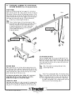
1) Slide the connection beam (1) into the back of the front beam
(2) to so the first hole aligns with the back hole of the front
beam as shown in Fig 3. Connect the beams together with the
provided 3/4" locking pin (5) and secure the locking pin with the
hair pin (6) provided.
© 2013 Tractel Ltd. All Rights Reserved.
13
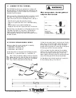
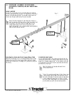
2) The middle beam (3) then slides over the remaining
section of the connection beam and joined at the front
hole of the middle beam as shown Fig. 4. Connect the
beams together with the provided 3/4" locking pin (5) and
secure the locking pin with the hair pin (6) provided.
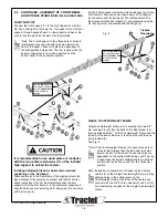
3) Slide the connection beam (1) into the back of the
middle beam (3) to so the first hole aligns with the back
hole of the middle beam as shown in Fig 5. Connect the
beams together with the provided 3/4" locking pin (5) and
secure the locking pin with the hair pin (6) provided.
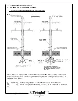
4) The rear beam (4) is then slides over the remaining
section of the connection beam and joined at the front
hole of the rear beam as shown Fig. 6. Connect the
beams together with the provided 3/4" locking pin (5) and
secure the locking pin with the hair pin (6) provided.
For Assembly in the horizontal position go to section 4.4,
for the inclined position go to section 4.5.
3
1
2
5
6
7
1
4
5
6
5
6
5
6
Fig. 4
Fig. 5


