


© 2013 Tractel Ltd. All Rights Reserved.
22
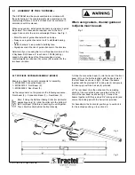
6. CHECKS BEFORE USING THE SKYBEAM
Before using on a new site, make an overall site survey, of
every place where an obstacle or dangerous items,
(I.E. electrical equipment or lines) may be located in the
possible way of the platform or of the suspension system.
Before using the platform, the following checks must be
carried out by a Competent Person.
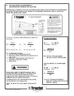
Ensure that the load does not exceed the
rated load of the platform, hoist or rigging.
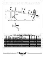
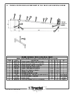
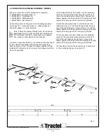
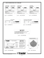
If you are using the two beam version of the
4’ skybeam 28 counterweights are required.
The three beam version requires 16
counterweights. Both beams have a 4’ reach
and a 1,000lb (454 kg). Maximum capacity.
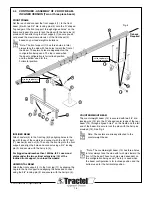
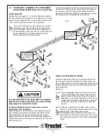
6.1 Suspension points and support equipment
a. Check that all connectors, pins, nuts and bolts are
securely installed and fastened and that the skybeam is
structurally intact.
b. Check security of skybeam and ensure that the required
number of counterweights are safely fitted and locked in
place. (See Fig. 12 & 13 on page 15).
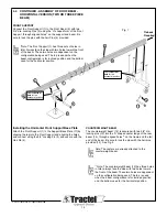
c. Ensure the safety tiebacks are installed without slack. See
section 5.0 Fig. 14 & 15 on pages 16 & 17.
d. Check that suspension points of wire ropes used with
each platform have been properly attached.
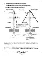
e. Ensure that the skybeam is directly above the hoist of the
platform in order to avoid excessive lateral forces side
loading on the support equipment.
(See Fig. 17 – page 19).
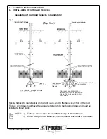
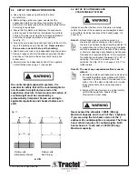
6.2 Tiebacks - ARE MANDATORY!
Tieback wire ropes with strength equivalent to the hoisting
ropes must be installed without slack. Tiebacks are to be at
right angles to the building and firmly secured to separate
safety tieback anchors, which meet or exceed load
capabilities of all local safety codes. In the event that the
tieback cannot be installed at right angles, See section 5.0
Fig. 14 & 15 on pages 16 & 17.
6.3 Platform
a. Refer to the manual of the platform manufacturer.
b. Check that all connectors, pins, nuts and bolts are
securely installed and fastened.
c. Check the mounting connections of the hoists.
d. Ensure that the platform is structurally intact.
e. Ensure that the load does not exceed the rated load of the
platform, hoist or skybeam.
f. Ensure that the platform is clear of any snow, ice, debris or
other material.
g. Ensure that guardrails are secured at proper height.
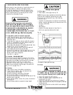
6.4 Wire ropes
a. Visual check of wire ropes. See Fig. 18
NOTE:
Only wire ropes specified by the hoist manufacturer
should be used. Regularly lubricate the wire ropes.
Wire ropes must be replaced if any of the following
defects are found:
- more than 7 wires broken on a length of 1 foot (300 mm).
- kinking, crushing, birdcaging or any other distortion of the
wire rope construction.
- corrosion.
- heat damage.
- reduction of nominal diameter of more than 5%.
- refer to wire rope manufacturer if in doubt.
Fig. 18
-
Examples of damaged wire ropes
6.5 Hoists
The 4’ skybeam
®
is designed for a Maximum load
of 1,000lbs. (454 kg). Do not use this system with a
hoist of a greater capacity then 1,000lbs (454 kg).
a. Refer to the appropriate hoist manual.
b. Check if the power supply is compatible with the
requirement of the hoist.
c. Check if the cable size of the power cord is sufficient.
d. Check that the hoists, Blocstop
®
and emergency switches
function properly.
e. Check that power cord has strain relief to avoid damage.
- Correct method of measuring wire rope diameter
Always wear gloves


